


Piridium Bus
Back to projectsDesign files and further documentation at this Github Repo
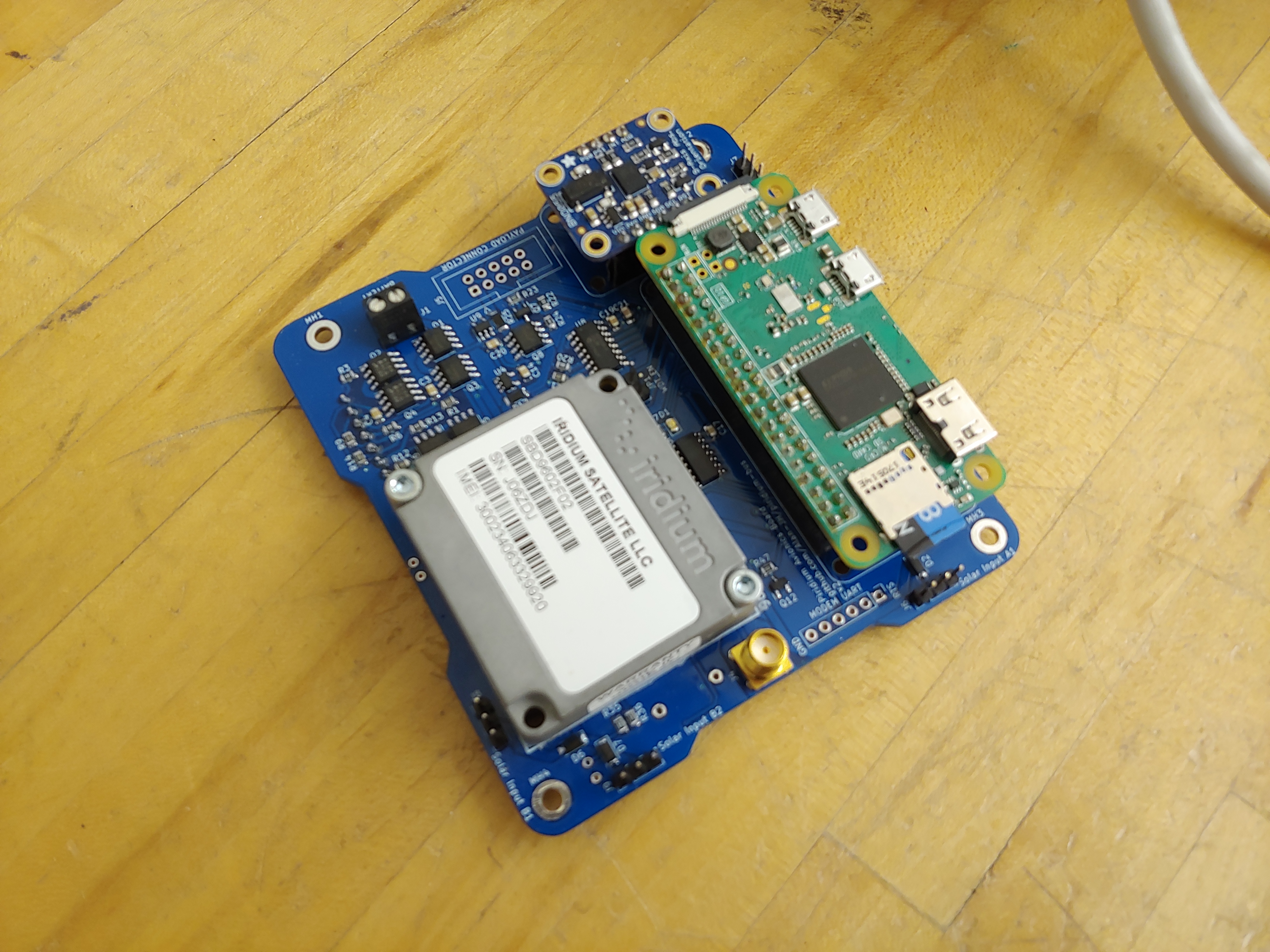
Piridium is a CubeSat bus design employing a similar design philosophy to Pycubed, but using an Iridium 9602N Modem and Raspberry Pi Zero flight computer incorporating design lessons from TJREVERB, the 2U CubeSat that I worked on. It is designed to be a low cost and easy to use CubeSat bus with basic payload interfacing. The Raspberry Pi allows flight software development in an operating system, which is more accessible to students than precompiled firmware. The Iridium modem uses the Iridium constellation for communication with the ground, which is a paid subscription service and eliminates the need for a hardware groundstation and antenna tracking software.
Design Process & Philosophy
I started the design in September '22, from a previous EPS project I had been working on. I worked in KiCAD, and started with the goals of keeping the design simple while still incorporating necessary protections and telemetry. The idea was to implement a bus around the Raspberry Pi Zero and Iridium 9602N Modem that TJREVERB used. TJREVERB used several stacked boards and converted UART to RS232 just for the modem breakout board to convert back to UART, so there was a lot of space and complexity to be saved. Additionally, the EPS and battery we used on TJREVERB included a lot of features we didn't need and never used, so I wanted to design my own power electronics for this bus (similarly to Pycubed).
Components were specced to AEC-Q100/101/200 Automotive grade where practical, as these go through more specific thermal and mechanical testing but aren't nearly as expensive as space grade components. The only downside is the lack of radiation testing. I added in latching current limiters to protect against latchup due to SEEs. As with most low cost CubeSat hardware, TID is assumed to be a non issue for most consumer hardware in low earth orbit, given the short mission duration (1 year or so) most CubeSats have.
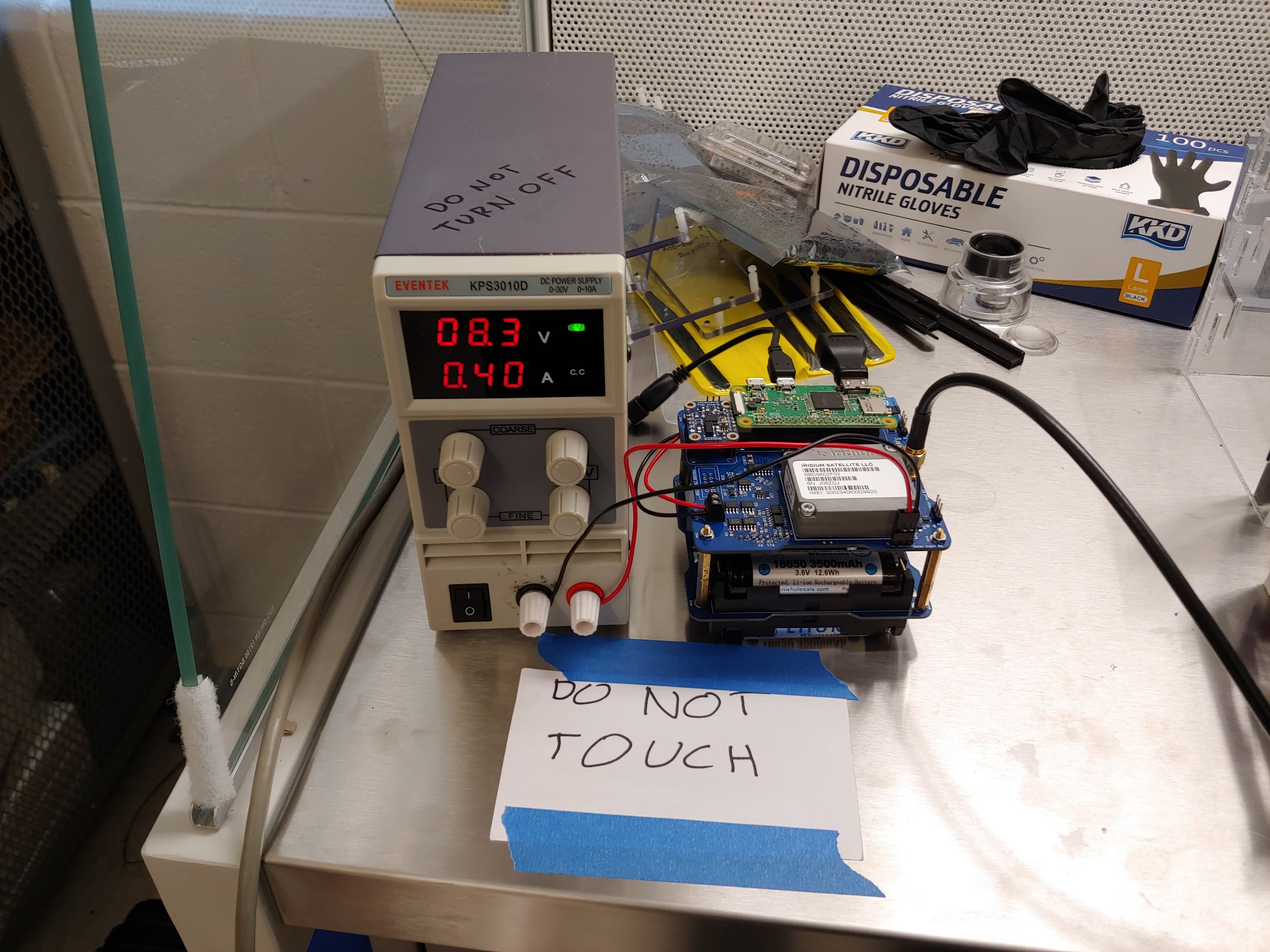
I ended up iterating three times from September to January, though I only ordered and assembled the first two iterations as the third iteration fixed an issue that could be fixed with a jumper wire modification. The second and third iterations both fixed design mistakes from the previous versions. I ordered and assembled the boards using surplus REVERB funding and parts, with my own solder paste setup and hot air station. I was especially anxious about whether the power electronics would work, so I assembled the first version section by section (5V regulators, then solar regulators, then inhibits), testing each section as I went.
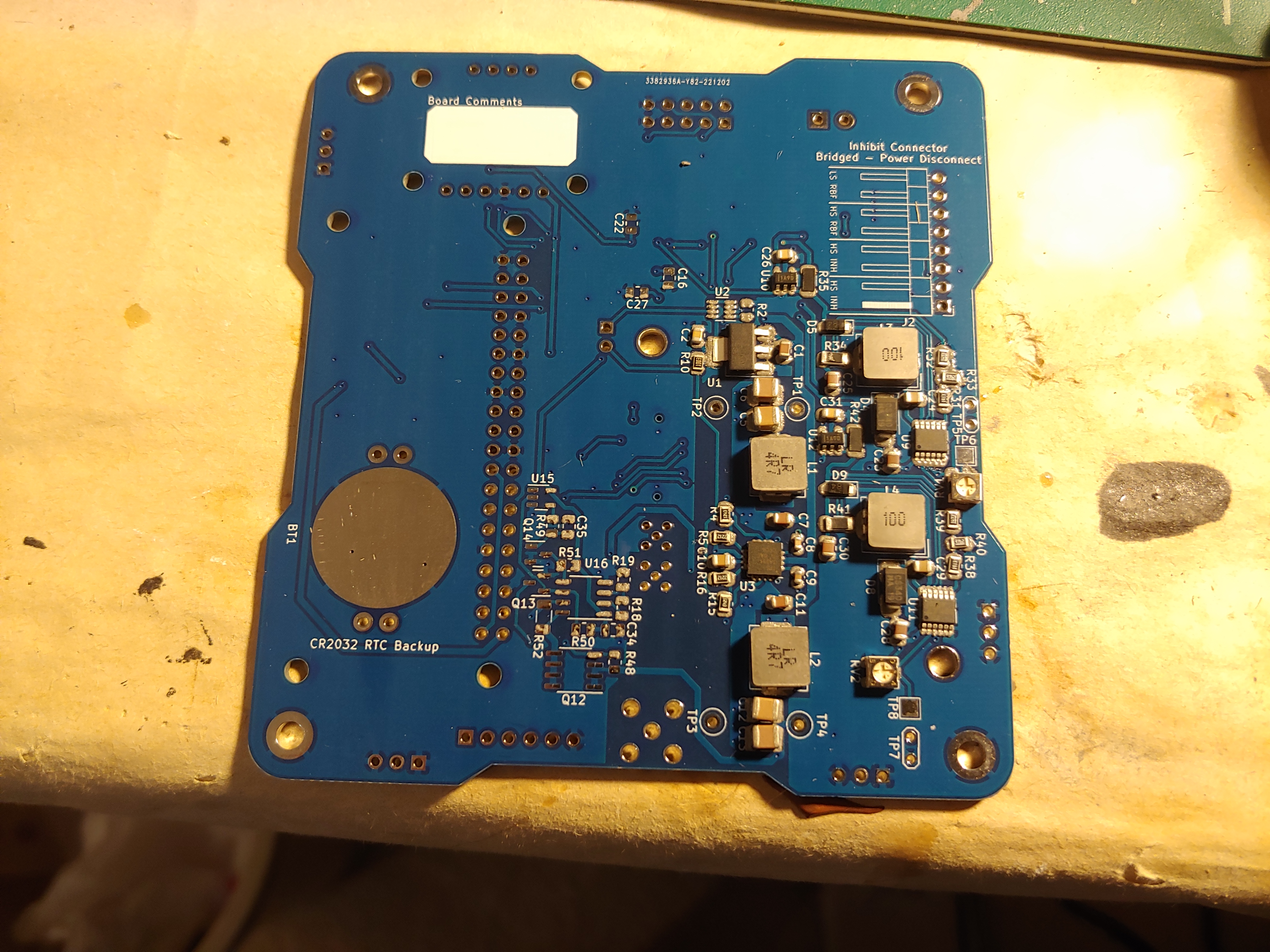 In the middle of assembling the power electronics
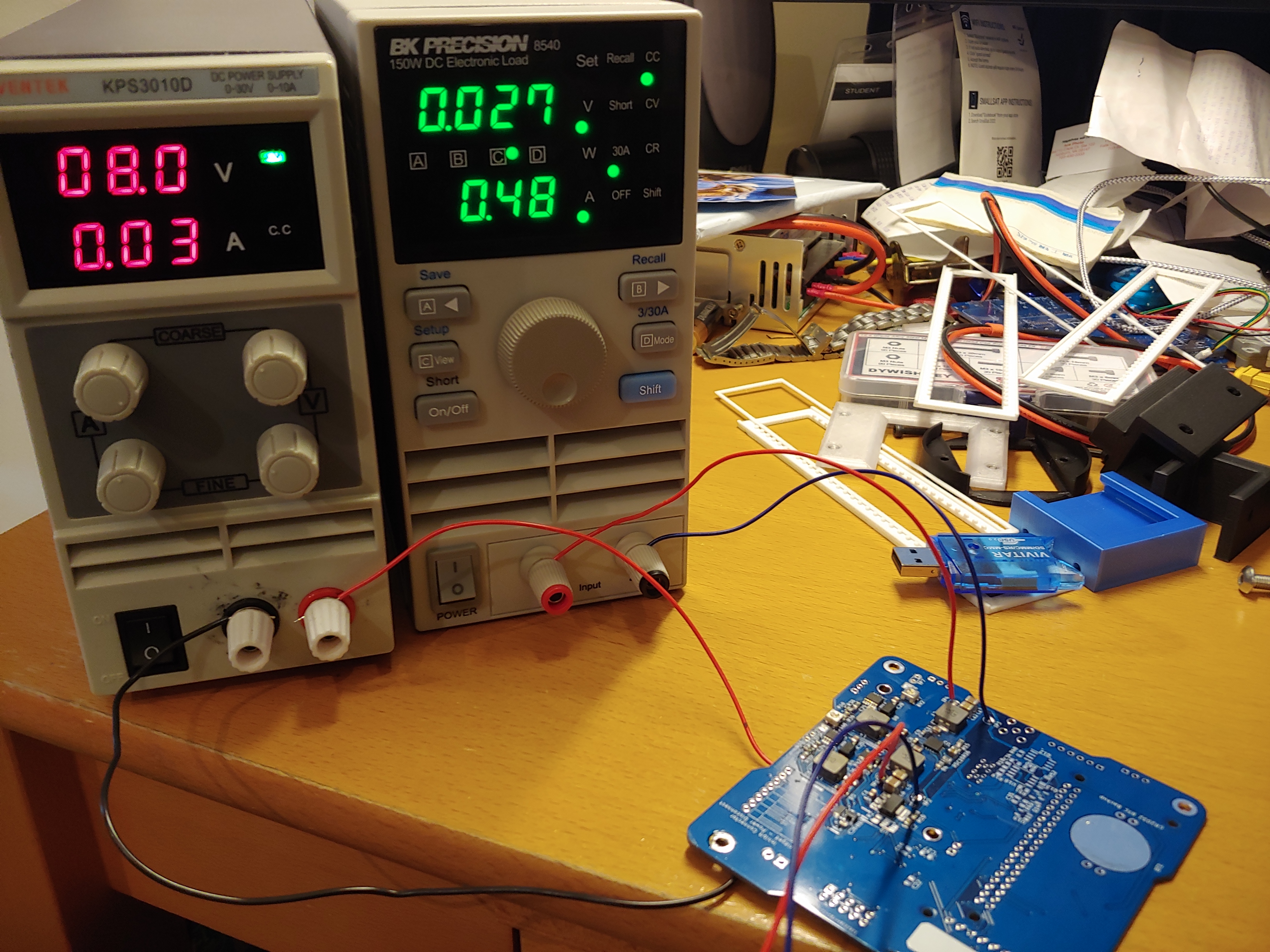 Testing the latching current limiters during winter break
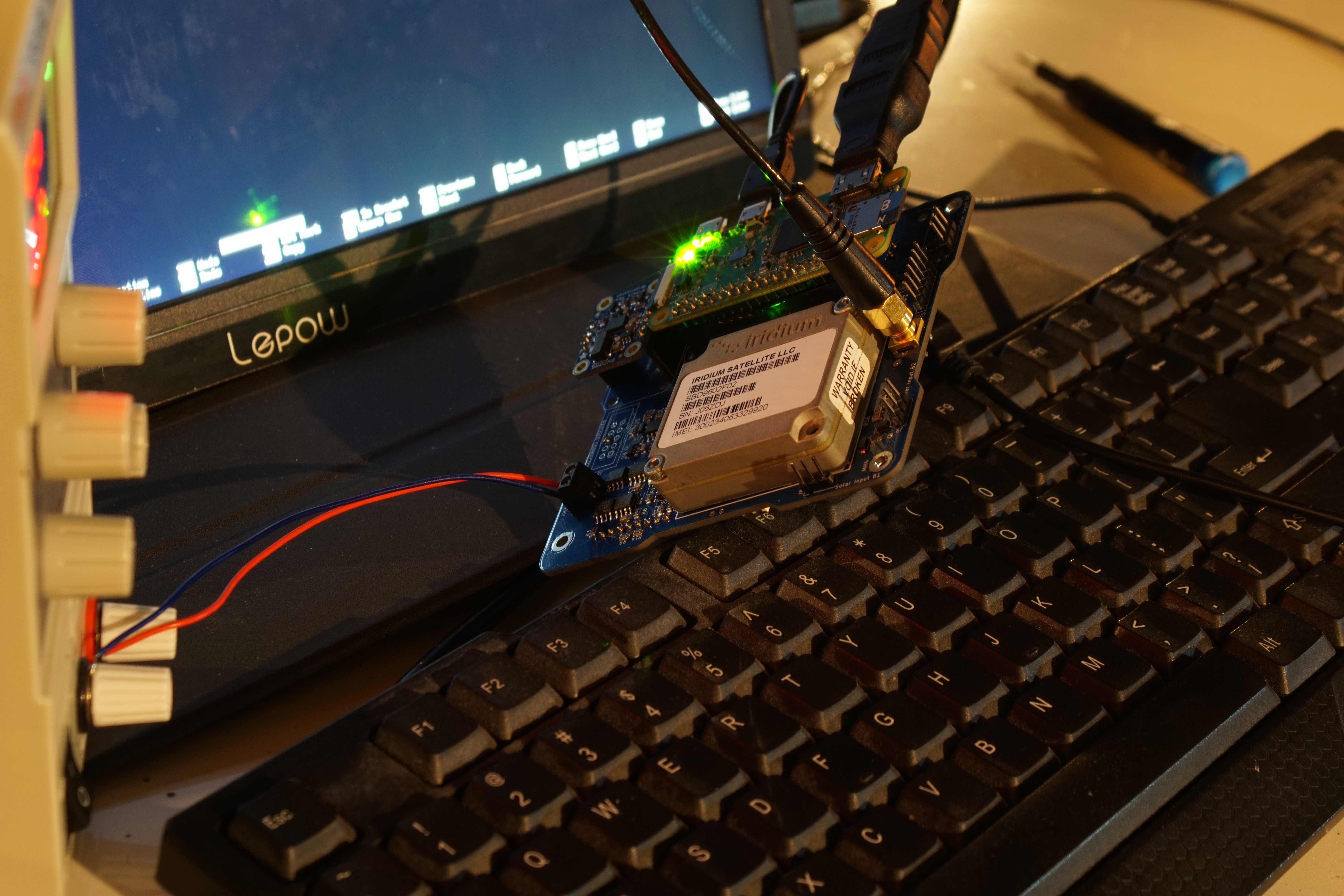 Testing Iridium connectivity outside
Tech Specs
See the Github README file for more info on chip selection and usage.
Issues and Future Work
The only major hardware issue after assembling the boards is that the battery balancing IC does not seem to work. This is very likely to be an issue with how I assembled the board, but I have not been able to debug it.
Due to the limited I/O on the Raspberry Pi Zero, I only broke out a few GPIO, 1 SPI, and 1 I2C to the payload connector on the avionics board, which is less than ideal for more complex missions that require more hardware interfaces.
Piridium is still untested for space conditions, as I never got the chance to thermovac or vibration test through my research lab at school. One of the biggest concerns is testing the cylindrical cell batteries, as these tend to have the most stringent test requirements from launch providers. It's safe to say Piridium won't be flying off the ISS anytime soon.
Last updated 11 Sept 2023