


TJREVERB Interface Board
Back to projectsWhen the 2022-23 TJREVERB team came in over the summer, the interface board, the PCB designed to route out connections from the stack header to the radios and flight computer, was an old version with incorrect routing corrected with jumper wires. After working with it and getting familiar with the design, I got to work on designing and fabricating a flight ready version.
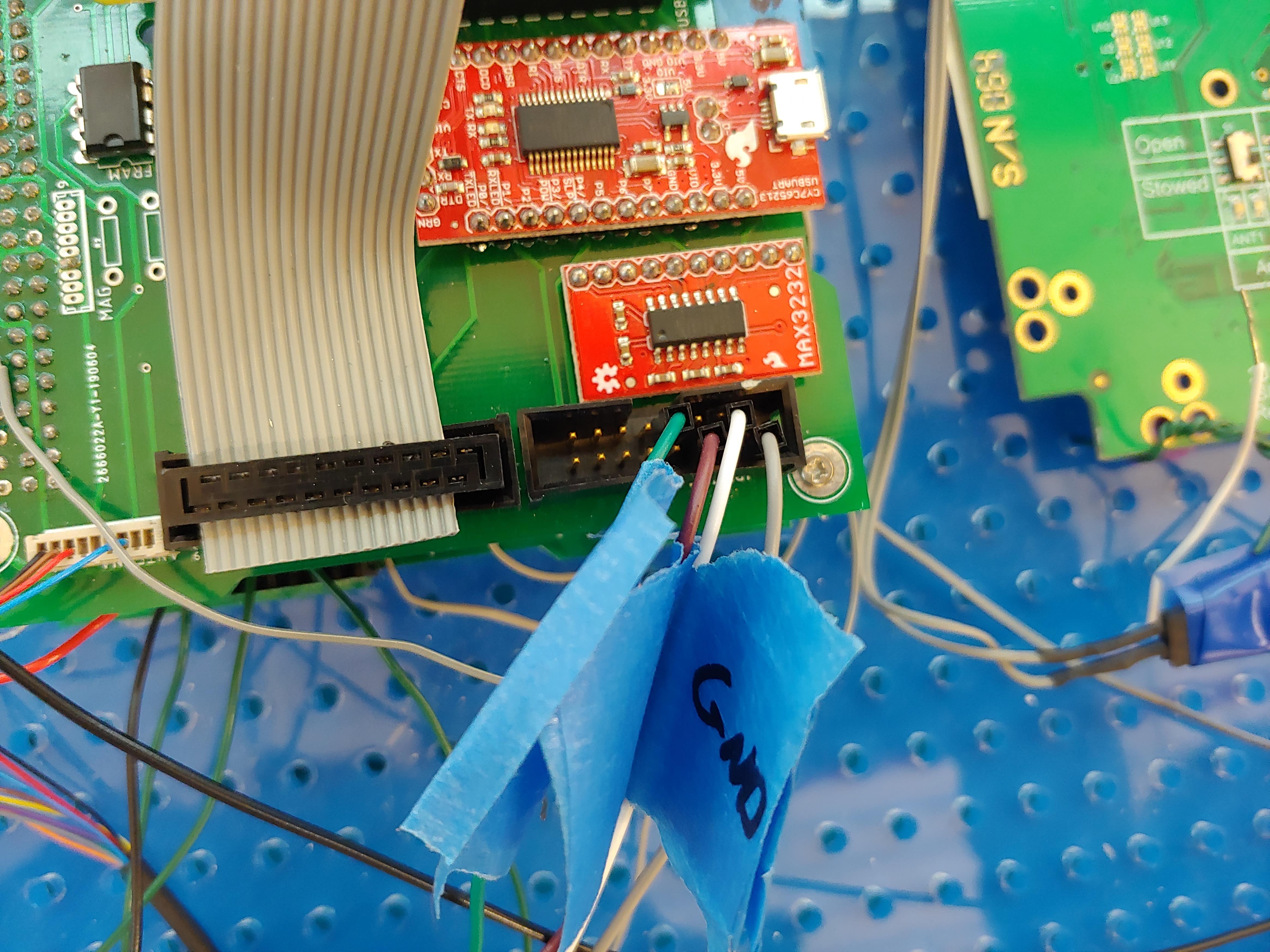 The Iridium ribbon cable pinout was wrong, so the previous team used male to female jumper wires to connect it
I reached out to the former electronics leads looking for design files, and a month later, they sent over some Eagle designs. I opened them in KiCAD and got to work on my own KiCAD schematic. I fixed up the pinouts and embedded SMD chips onto the board rather than using breakout boards, mainly to save space.
I also designed in some system improvements. First, I put in solder jumpers to be able to select between hardware UART and USB to UART for the two radios. The Raspberry Pi Zero only has one UART interface, but TJREVERB has two radios using serial interfaces. So the previous design used a USB to UART converter connected to the Zero's USB port for the APRS radio. Since the Iridium radio is RS232 and needs a UART to RS232 bridge, this gives each radio one converter and equalizes the points of failure (roughly; the USB to UART bridge is way more likely to fail as a digital device than the RS232 bridge, which is a basic charge pump). But since we were using the APRS as the primary radio at the time, I wanted the option to use hardware UART for the APRS radio and two converters for the Iridium.
Second, I powered the serial converters off of EPS power distribution modules (PDM), which are basically switched outputs, because the previous version of the inteface board powered them off of permanent buses, which meant that they could only be reset if we power cycled everything on the interface board, especially annoying for the USB to UART converter, which froze often. With the EPS PDMs, we could reset each component individually by a single command to the EPS.
Third, I began to implement a version that used an SPI to UART converter. I wanted to move away from USB, because of the aforementioned freezing and the jank soldering to the USB test pads on the bottom of the Raspberry Pi. I selected the SC16IS752 I2C/SPI to UART bridge. I designed two "branches", one with the original USB to UART converter, and one with the SPI to UART.
Finally, I put test points and LEDs to indicate which PDMs were switched on, and give places to measure bus voltages.
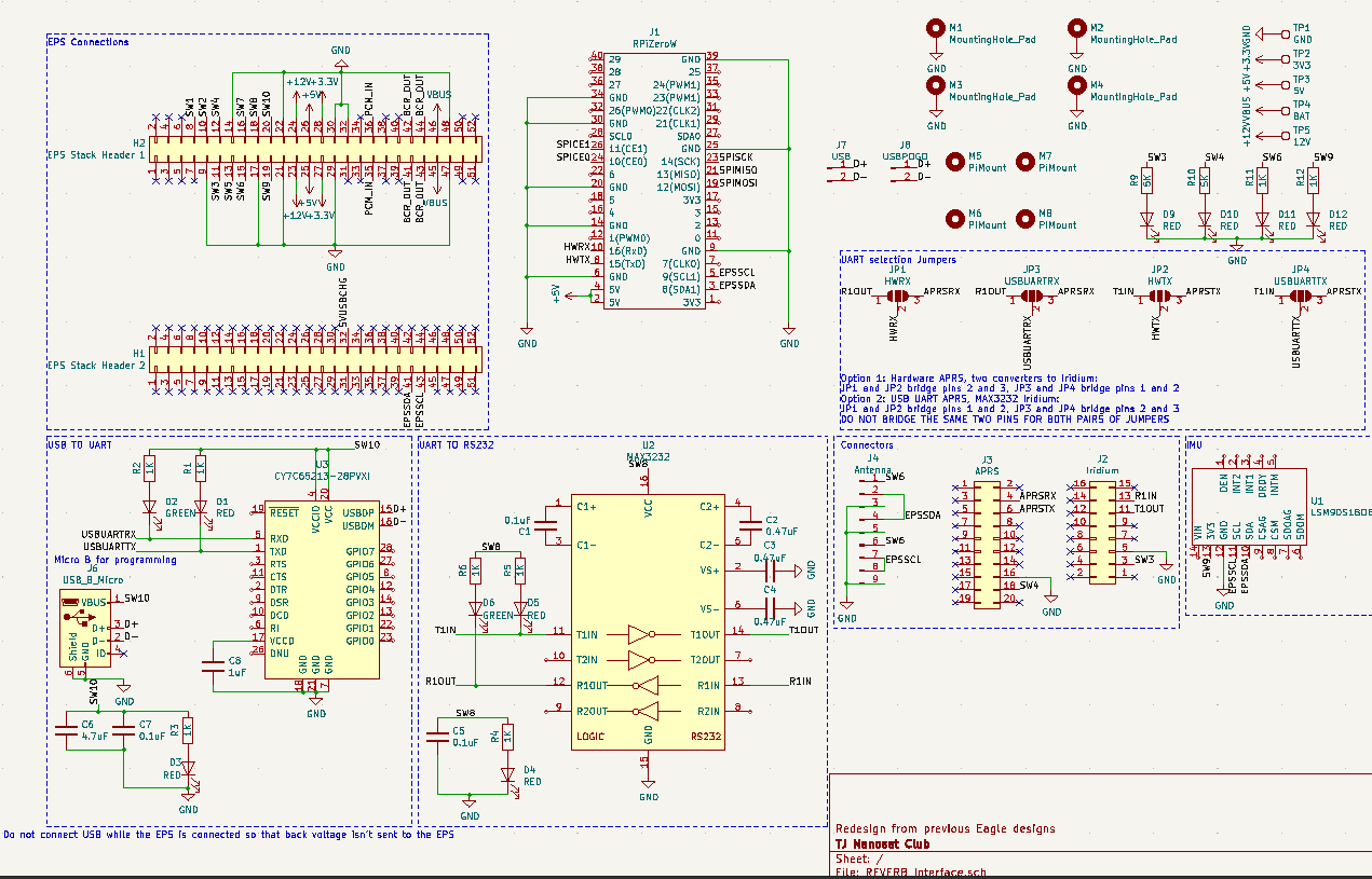
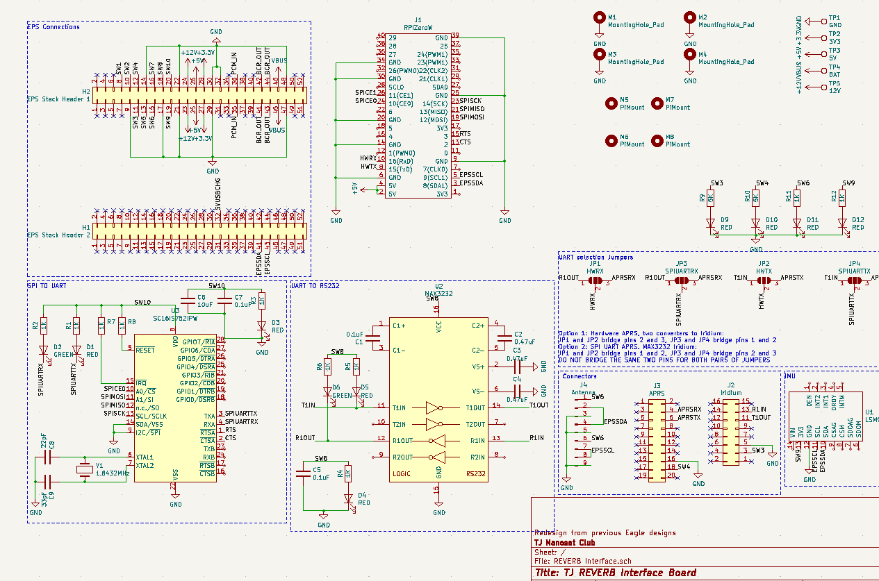 The schematics for the USB and SPI branches
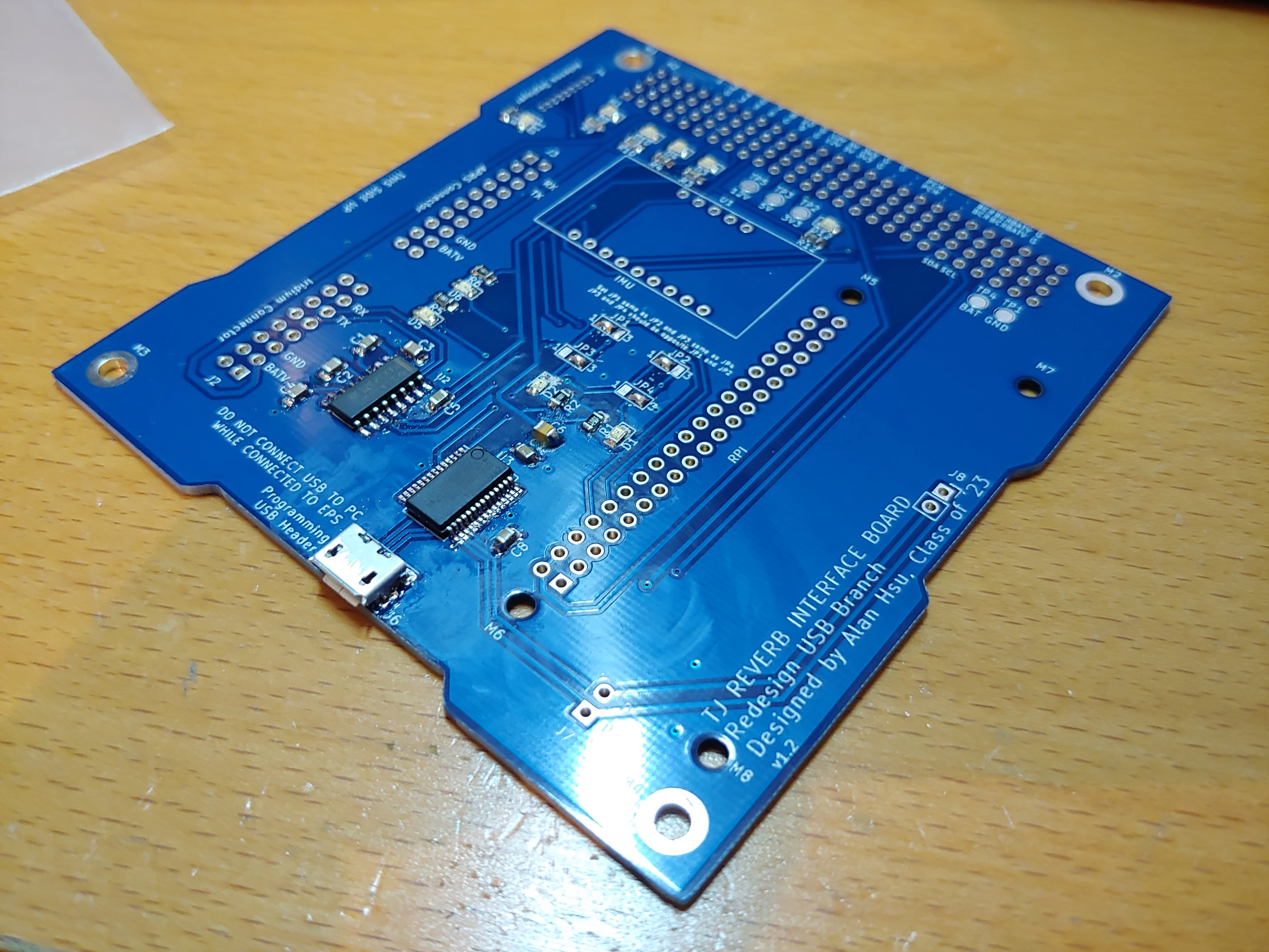 Assembled v1 USB version
After I assembled and tested, I found a couple issues. First off, I didn't realize that the APRS used 5V logic, while the RPi had 3.3V logic. I had to bring in my own level shifter and put it in line between the board connector and the APRS ribbon cable. I made sure to fix this in the next version, with a TXB0104D level shifter on the board. Second, I couldn't write a working driver for the SPI to UART bridge. So I decided to switch to I2C and use an ATTiny IC for the next version, which I would program to repeat the data it received on I2C over its own UART connection.
The IMU that was on the previous interface board was out of stock and we only had one extra in the lab, so I switched to the BNO055, of which there were plenty in the robo lab. One member of the programming team suggested we put a real time clock backup on the satellite so that we could set time and maintain time during system resets. I chose the DS3232M IC, which is a temperature compensated I2C RTC with a built in MEMS oscillator. I used a Murata CR2032X backup battery for its temperature rating. I was running out of space, so I ended up routing this IC under the Raspi and mounting the battery on the bottom of the board. I also added the USB switch back in and the 5V charge port, which I had removed in v1 because I didn't know what it was for.
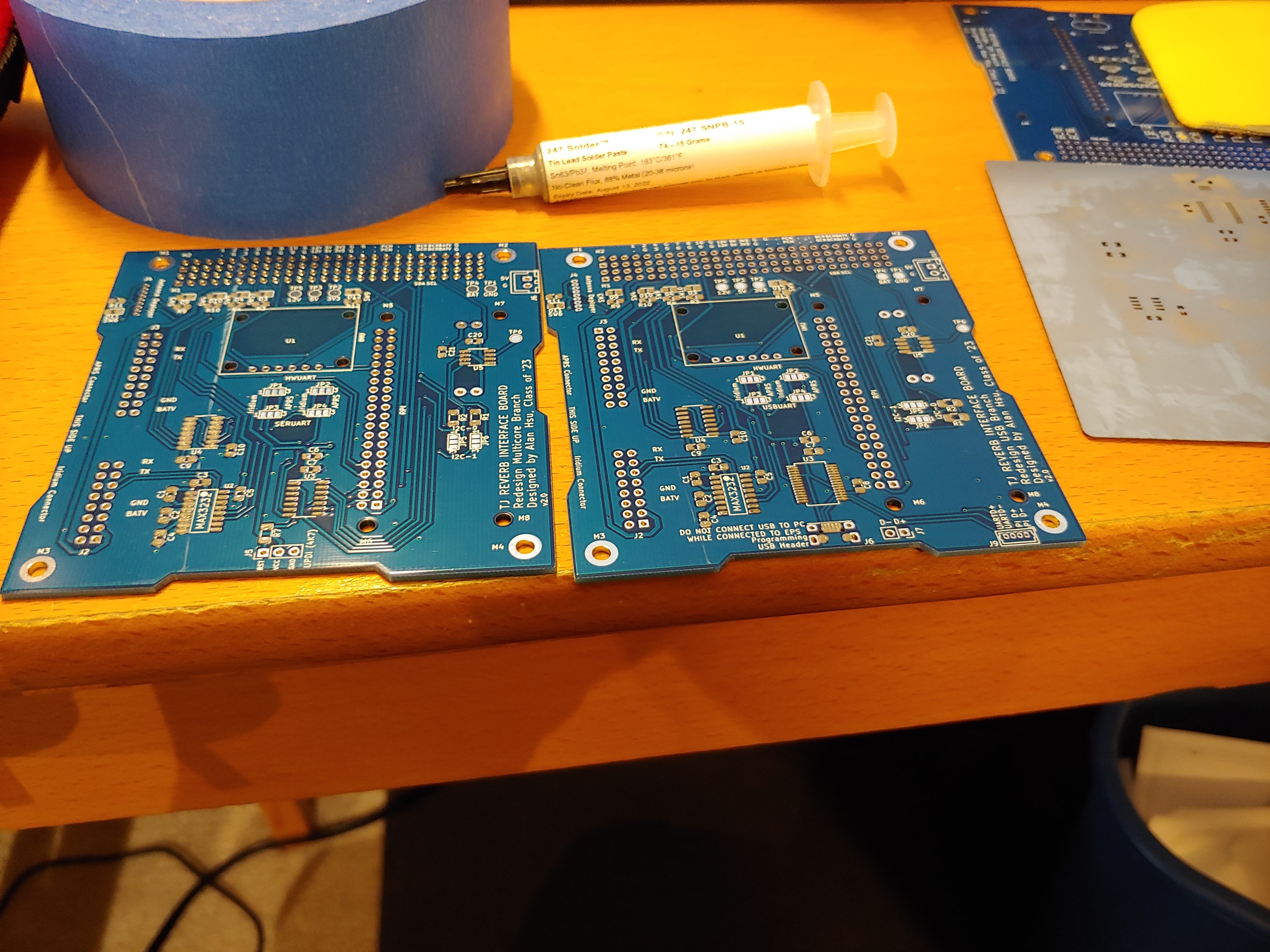
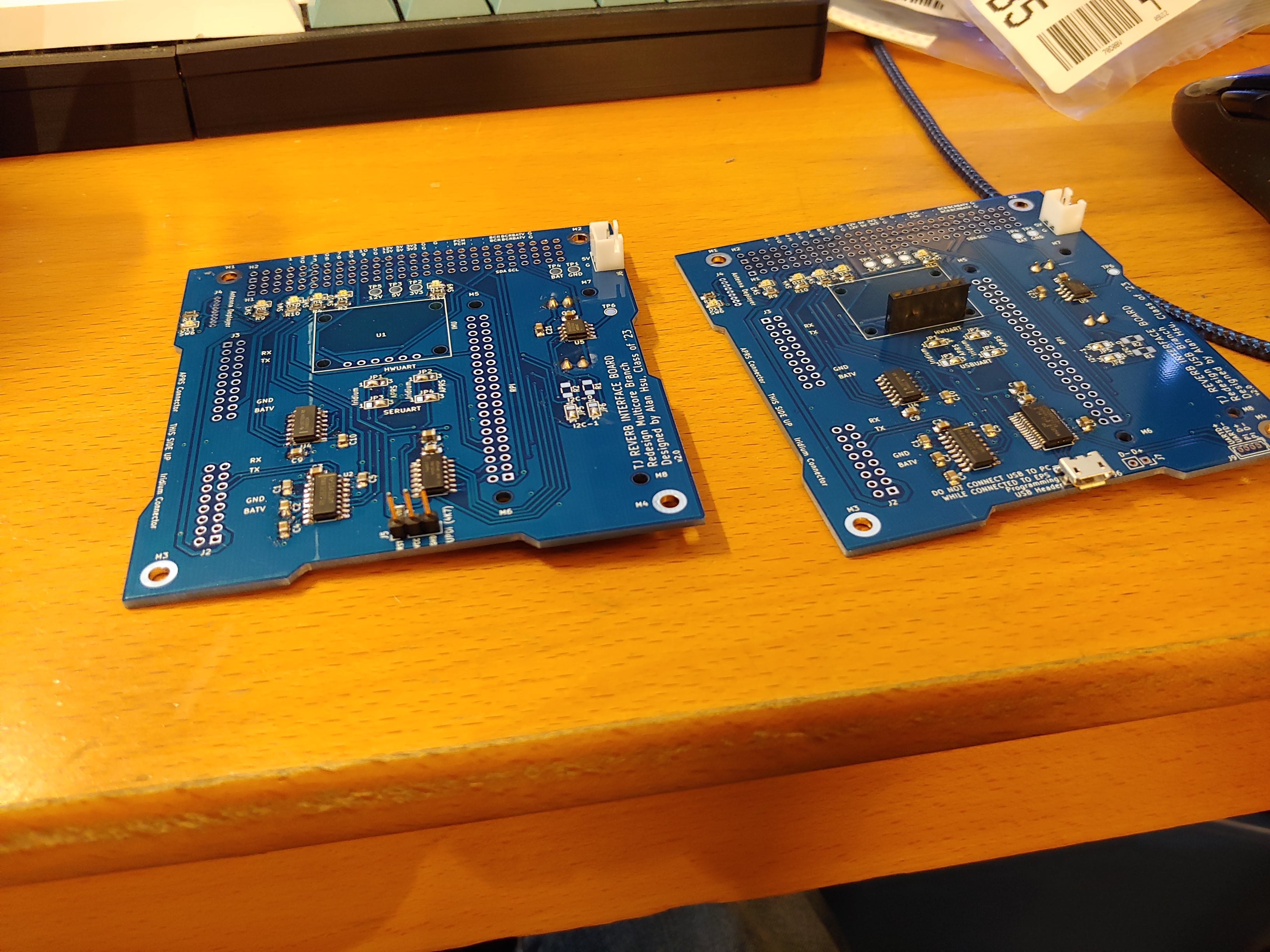 Pasted and assembled v2 USB and I2C versions
Version two was successful, and the first time I could plug all the cables into their board connectors without wire modifications or level shifters. I wrote and tested drivers for the RTC, but ended up just using the builtin overlay for the DS3231 in Raspbian, which sets the system clock to the RTC time on boot. I tried to write and test the code for the ATTiny I2C to UART bridge, but was once again unsuccessful before winter break. As we went on break, it became clear that the USB to UART converter was working fine when we could reset it with PDM power, so I decided to deprecate the I2C to UART version. We performed final assembly with the USB to UART version.
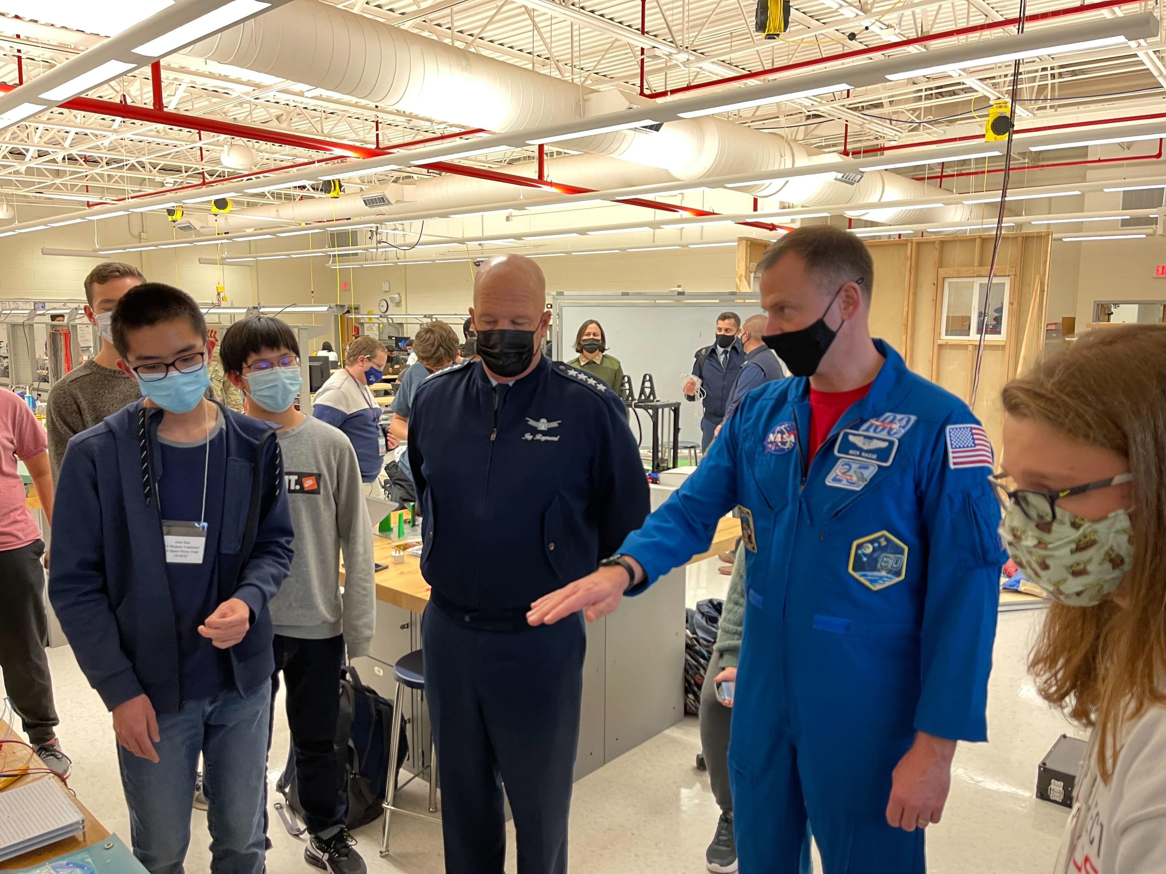 Me explaining the interface board and flatsat setup to Space Force Gen. Raymond and Col. Hague, when they visited the school in December
Of course, it wasn't perfect. I had to make a couple more modifications before final assembly. First, I had mistakenly placed the IMU on a 5V PDM thinking that its 3.3V LDO would need 5V to regulate out 3.3V. The Adafruit BNO055 board actually uses an ultra low dropout regulator which can regulate from 3.3V, and uses a level shifter to shift its I2C data lines to the Vin voltage. Since the Raspi has 3.3V logic, this means I should've powered the IMU with a 3.3V PDM. So instead of fabricating a new board, I cut the pin on the stack header for the 5V PDM and soldered a wire jumper to connect that pin to a 3.3V PDM. The modification is visible in some pictures as a glob of epoxy on the stack header, to keep the wire in place during vibration.
I also had to permanently solder wires to the USB switch, which was a DPDT switch that switched the USB data lines from the Pi between the debug USB port on the top of the satellite and the USB to UART converter for the APRS radio. The 4 pin Molex connector couldn't plug in properly, and we weren't going to use the debug USB port anyways.
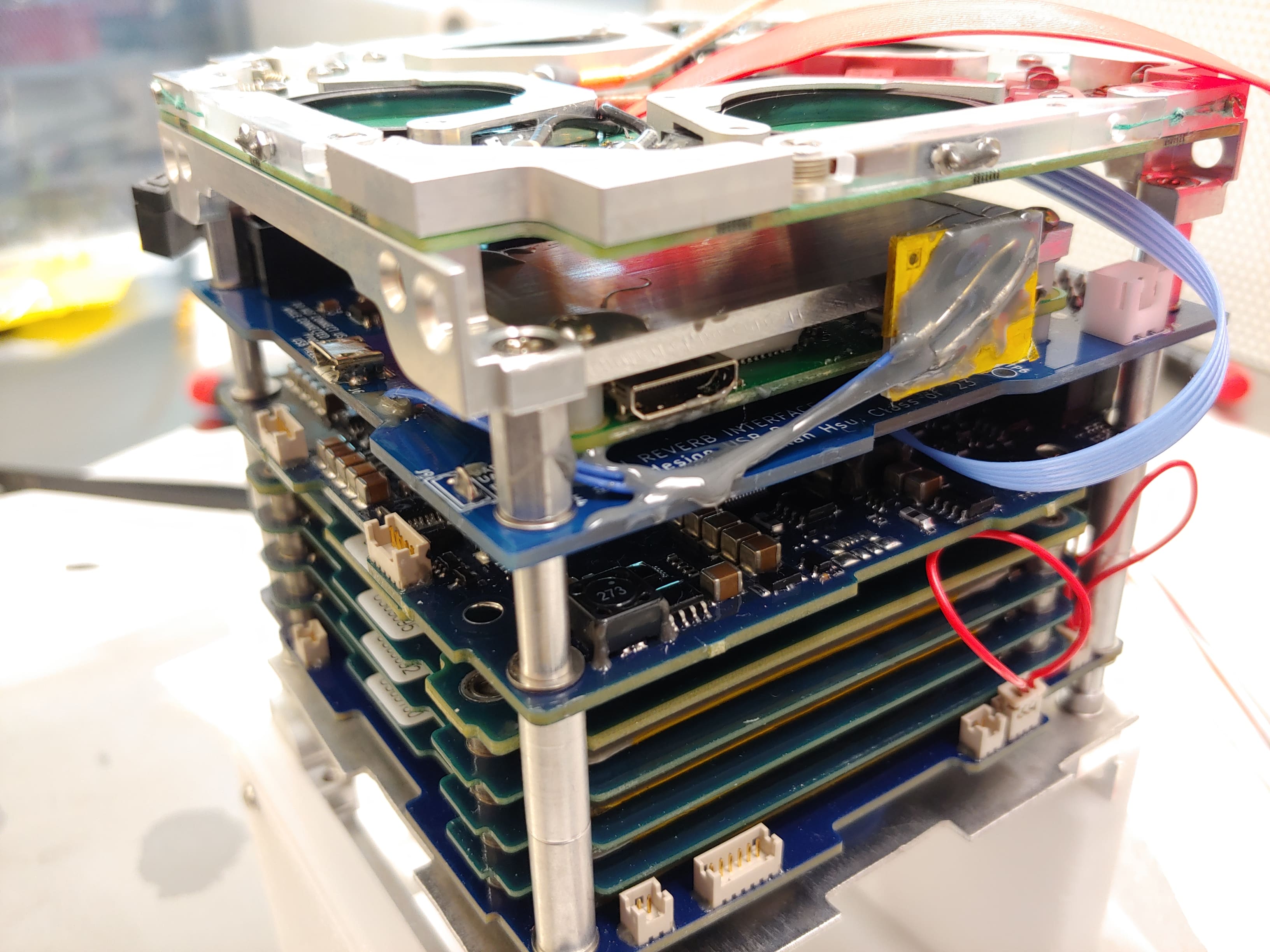
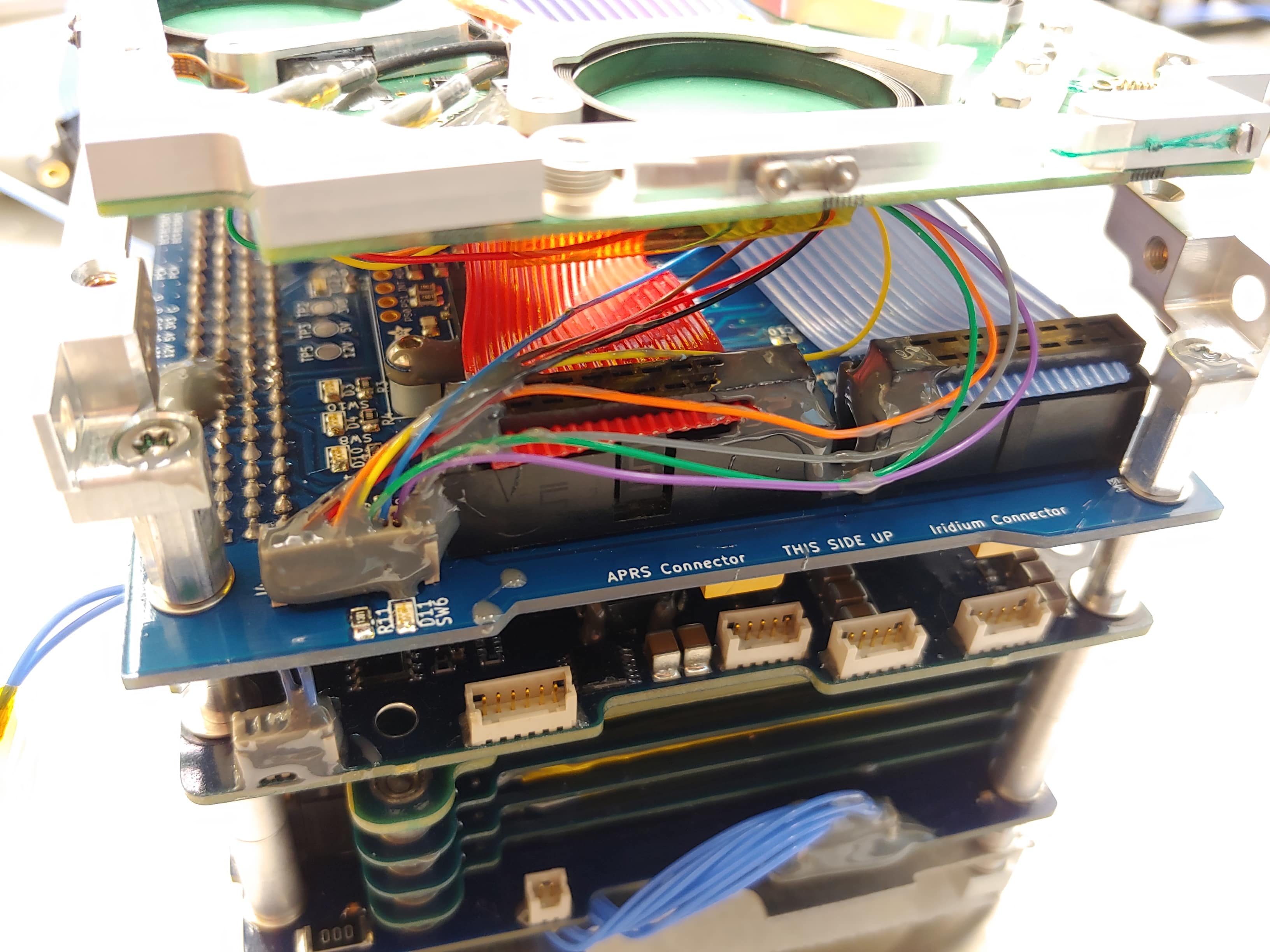 The interface board on the stack during final assembly
Lessons
The interface board design was a success, but I could've saved a lot of time and effort by just realizing after v1 that the USB to UART converter was a good enough solution, and trying to implement an SPI to UART converter would be spending time for marginal benefit. The interface board is now in space, operating on TJREVERB as it gets deployed from the ISS.
Last updated 13 Dec 2022