


FOC Motor Controller
Back to projectsWhile I was interning at Starpath Robotics in the Summer of '22, I worked on an FOC motor controller design, as an in house designed alternative to the O-drive system that we had trouble working with. The TL;DR is that the theory is very interesting and neat, but putting it into practice is extremely difficult, and I eventually gave up the project.
The Theory
FOC stands for Field Oriented Control, and refers to a type of brushless DC motor control that control loops to maximize the current vector perpindicular to the rotor, maximizing torque. This is an improvement over traditional Electronic Speed Controllers that produce a three phase trapezoidal or sine wave at a certain frequency, and measure back EMF to determine speed and how much to change the frequency to keep the speed at a certain set point. Traditional ESCs struggle to provide consistent torque at low speeds, and do not provide as much torque at peak, because the current vector perpindicular to the rotor is not always maximized. FOC can run motors at high torque and low speeds, with good positioning accuracy, and maximizes peak torque.
Basically, FOC allows you to use a BLDC motor as a stepper motor but without the efficiency and max speed sacrifices that come with stepper motors. FOC is often used in electric vehicles for torque efficiency, and in gimbals for a lightweight and responsive motor drive system.
The actual theory behind FOC is a little more complicated. We can consider the three phases of the motor as coordinate axes, and we can convert the three current vectors along those axes into two current vectors along the axis of the rotor and the axis perpindicular to the rotor and back using Park and Clarke transforms. Id (the vector parallel to the rotor axis) should ideally be zero, as any amount of current in this direction is wasted as heat. Iq (the vector perpindicular to the rotor axis) should be maximized, and is also what the inner control loop controls for. So, the system reads the three phase currents using current sensors, then converts them to Iq and Id vectors (using position data from an encoder), then uses a PI loop to set Id to zero and Iq to the setpoint by varying the PWM duty cycles of the three motor phases. It should be noted that the inner loop is controlling for torque, so any speed or position control would need a second control loop to change Iq based on what the current speed or position is.
Here are some of my notes from when I was learning the theory at Starpath: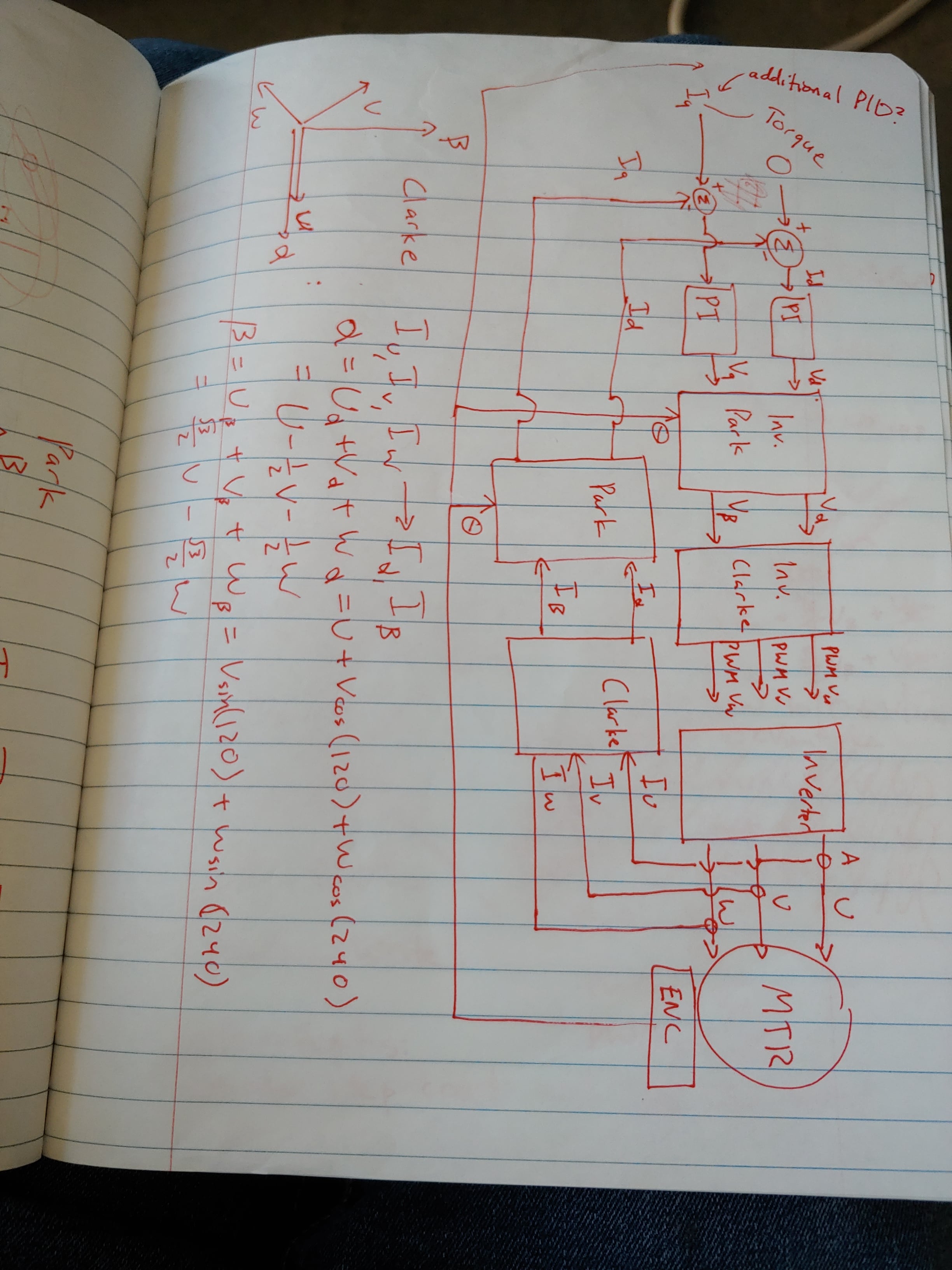
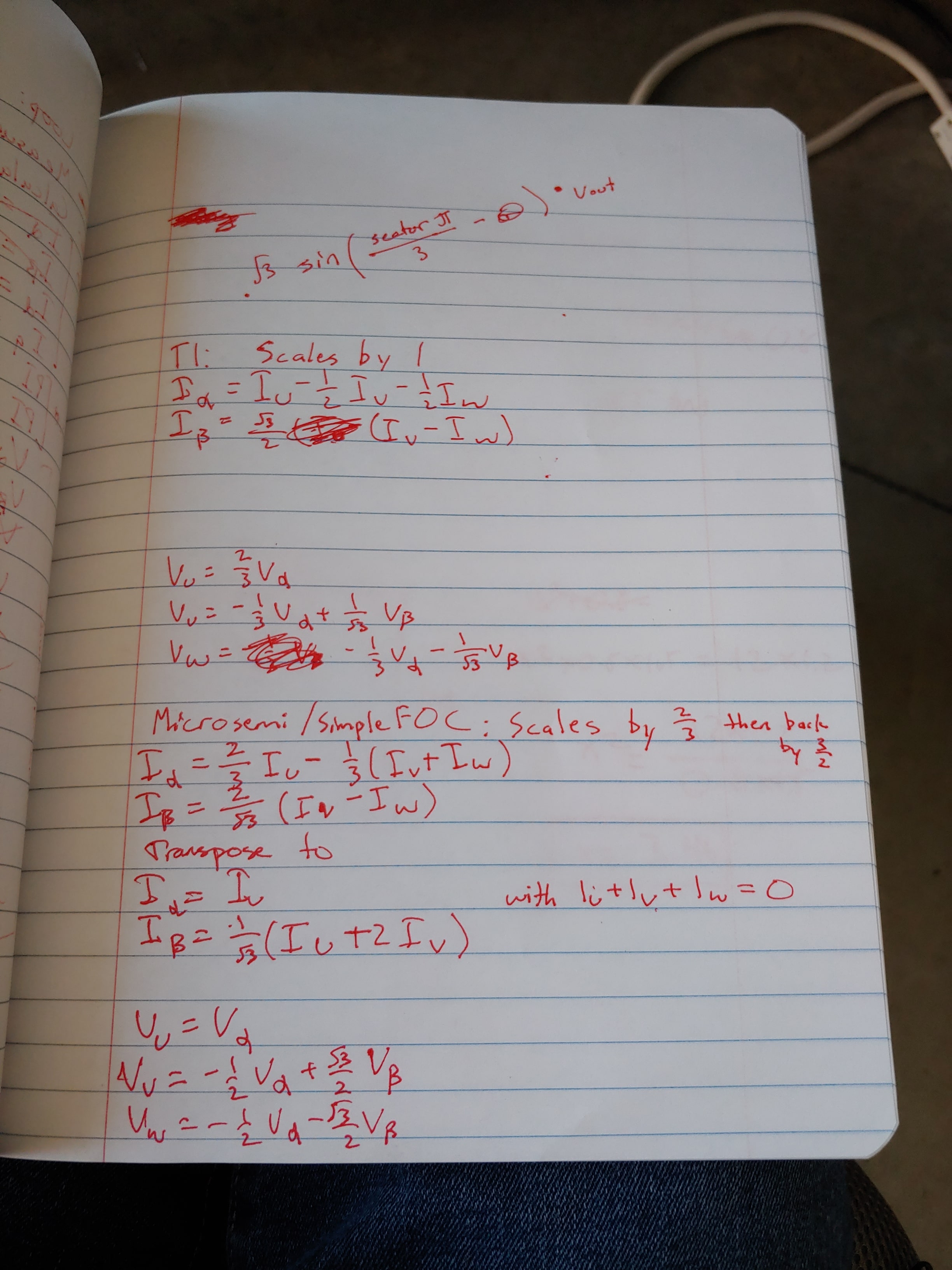

This video by Texas Instruments explains the concept very well, but the Park transform formula is incorrect
The Practice
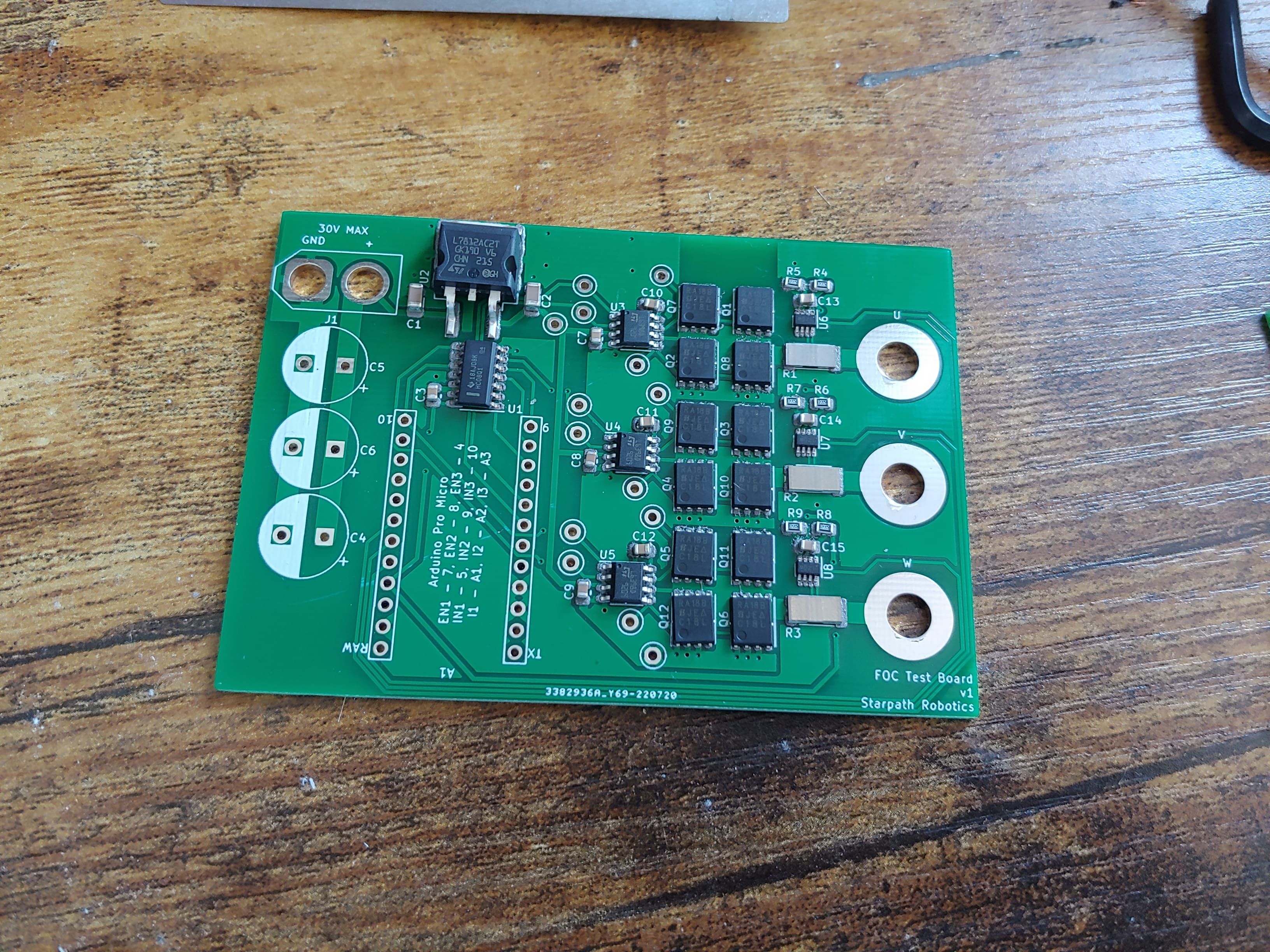
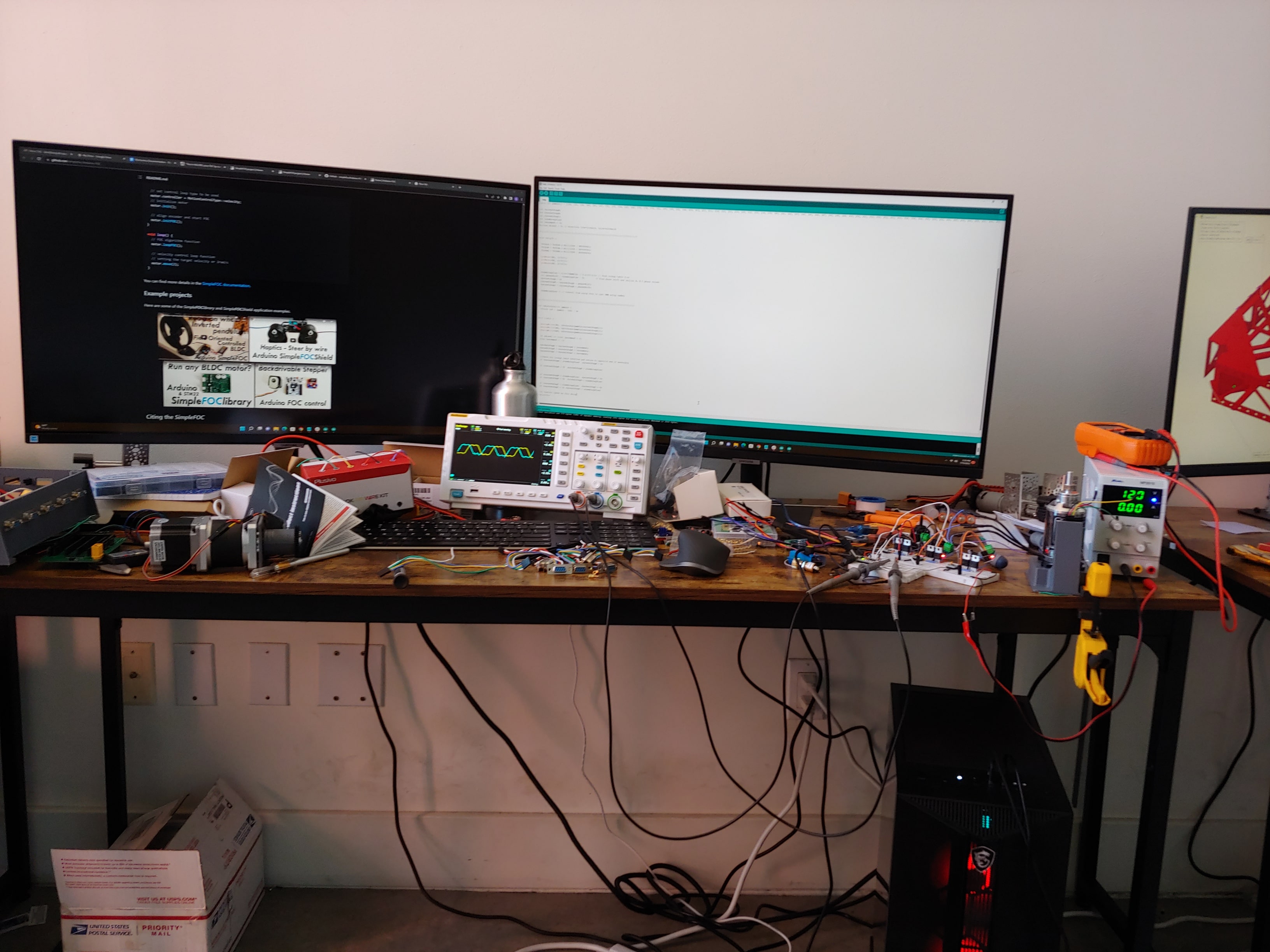
Putting it into practice is much harder. At first, I put together a breadboard prototype first to confirm that I could design an ESC at all, and second to try the FOC algorithm on it.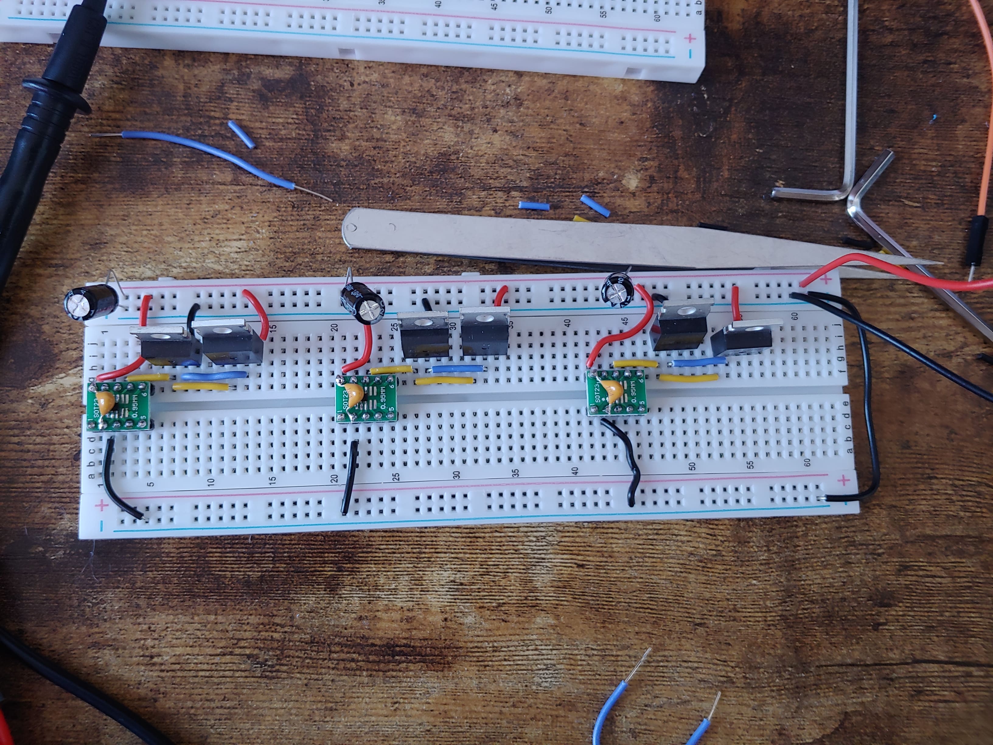
Lessons learned from this project were that theory is sometimes very hard to put into practice, and being able to trust your instruments and sensors is extremely important. I also gained a healthy respect and fear of debugging control loops.
Last updated 23 Nov 2022