


PCB Reflow Hotplate
Back to projectsAt the start of junior year, I saw a video by Carl Bugeja about using an aluminum PCB as a hotplate for solder reflow. I really liked the idea, so I stole it. I decided that I wanted a larger plate area to be able to reflow larger PCBs, and I wanted a separate PCB for control rather than putting the control circuitry on the same aluminum PCB.
What is reflow?
Surface mount components are most often soldered by a process called reflow. Reflow is basically any method of melting an area of solder rather than soldering each individual joint. Hot air stations are one way to reflow, and the way that I most often assemble PCBs nowadays. Most industrial PCBs are reflowed with ovens that heat up all the solder at once. Heatplates are another method, less common than ovens, but somewhat more user friendly. Instead of using air, heat is transferred by contact.
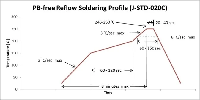
Reflow isn't as simple as just heating the board, though. In order to prevent damage to the components on the board, and in order to prevent artifacts like tombstoning, where water vapors cause a passive component to flip up, the temperature profile must be very specific. A typical reflow profile for lead free solder is shown below. There is a slow ramp at the start, and a sort of pause around 150C, which serves activate flux and boil off any water without tombstoning, followed by a fast spike up to 250C to actually melt the solder. The ramp up and cooldown of the spike need to be fast, and the time at peak temperature needs to be short to prevent damage to the electrical components.
My Project
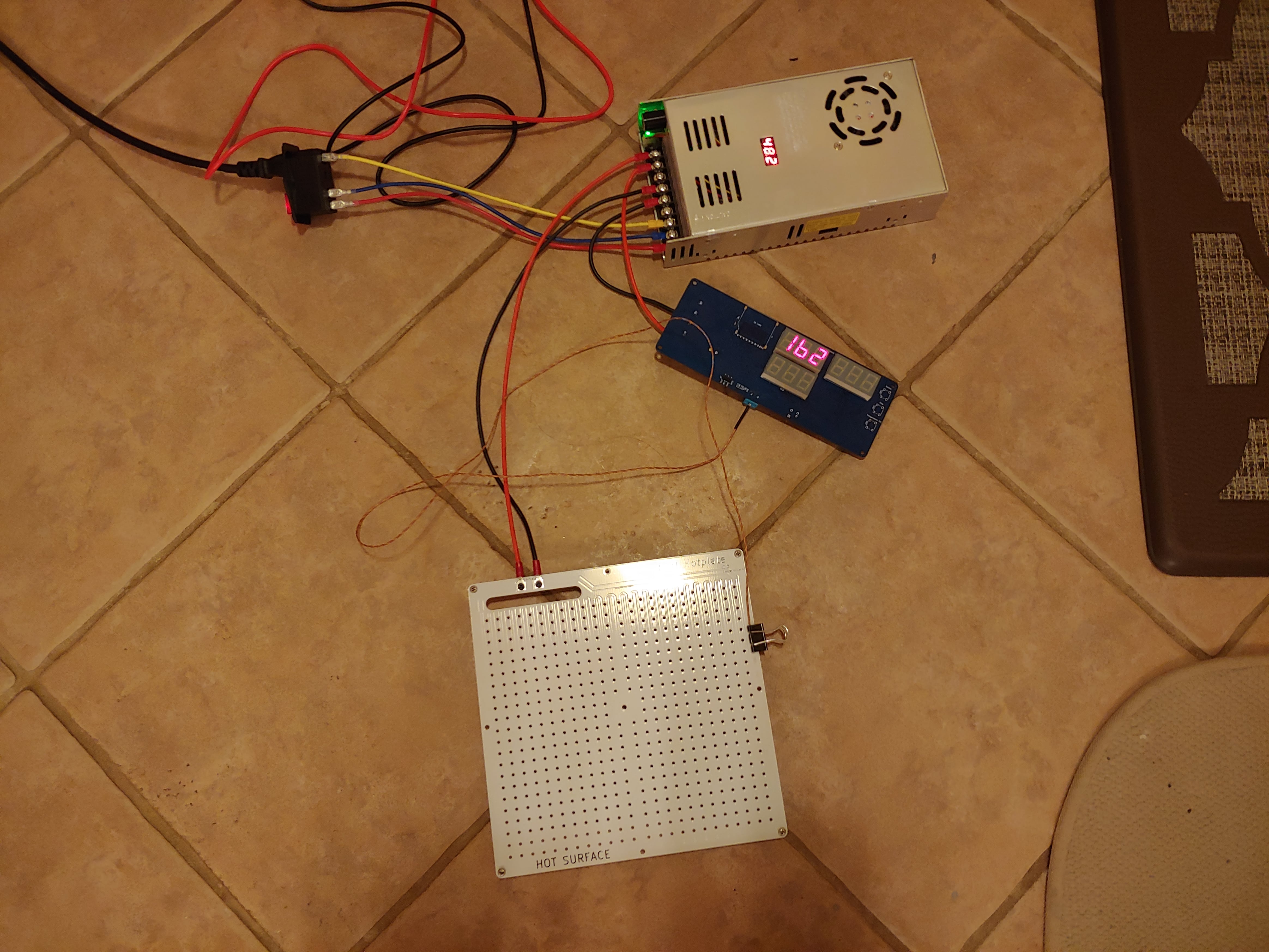
The idea Carl Bugeja presented was using an aluminum PCB as the actual heating element, inspired by the FR4 PCBs already used on Prusa 3D printer heat beds. My design took that idea, and applied it to a 200x200mm bed size. I chose to separate the control electronics and just make the aluminum PCB a pure heating element. The design is a simple long trace, with the trace length calculated for 5 ohms of resistance. I added a grid of holes to reduce the thermal mass of the plate. I had to go through two design iterations of the PCB because the 1oz copper JLCPCB used did not match the resistivity of the 1oz copper of the calculator I used, and resulted in a 7 ohm trace rather than a 5 ohm.
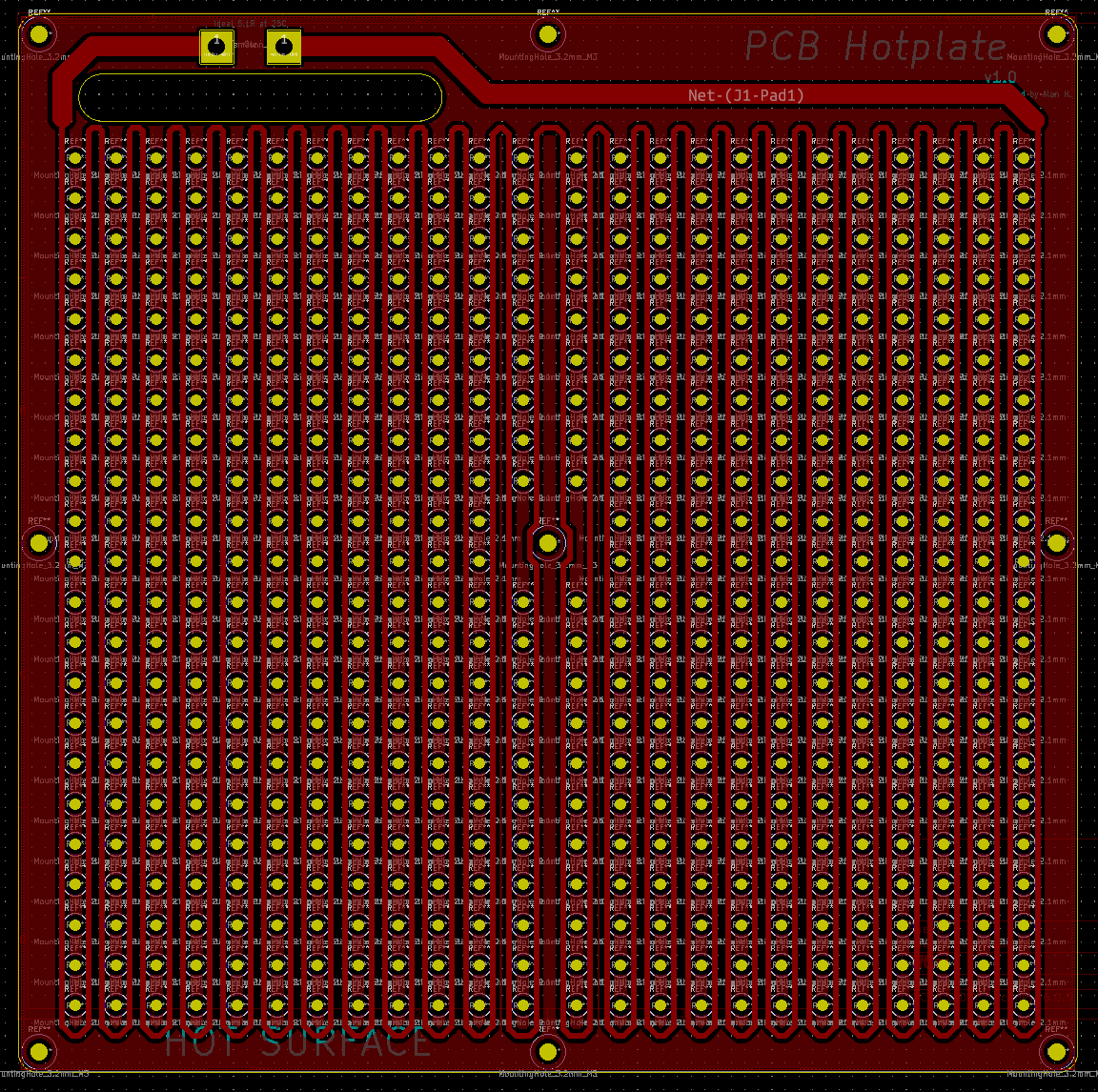 The final version of the heating element PCB
The control board was a normal FR4 PCB, with a 48VDC input, buck converter for the control electronics, an ATTiny1624 microcontroller controlling everything, a MOSFET for switching power to the heater, a thermocouple amplifier, an SD card for storing reflow profiles, and a display interface for showing target and actual temps and time. This was actually my first time using a buck converter, and the first time I realized the limitations of linear regulators in high voltage drop applications. This was also my first time using the ATTiny processors for a project, and I really became addicted to ATTiny 0, 1, and 2 series microcontrollers for small embedded projects since then. An ATTiny 1624, for example, has similar specifications to an ATMega328 but with much less IO, and costing only 80 cents.
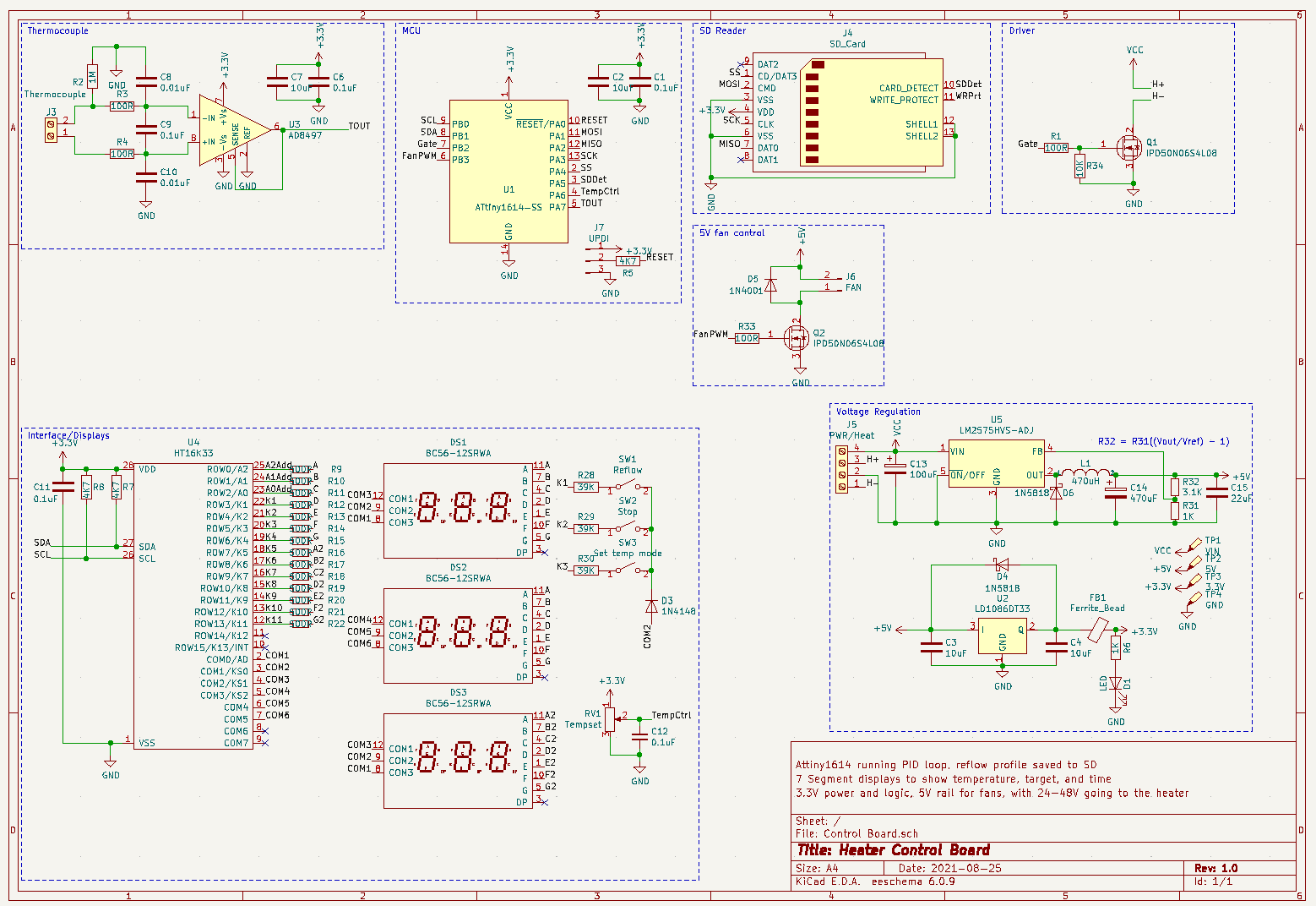
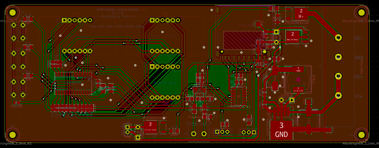 The schematic and board layout of the control board
Results
The first version of the heater failed to reach my target of 200C (for leaded solder) at all, peaking at around 185. The second version was able to reach 210C, but took several minutes to climb from 190 to 210, which is unacceptable for a reflow profile. The issue is that the thermal coefficient of copper is much higher than I expected. Though the hot plate was 5 ohms at room temperature, at 200C it was 20 ohms, which significantly cut down on the power output with a fixed 48V supply. This meant that the temperature profile of the hotplate looked the opposite of what a reflow profile should look like, with the temperature rising much slower once it reaches a high temperature. I burned an entire control board's worth of components while testing it out for this reason. Another issue was that solder that was connected by copper traces to through hole pads or vias would melt long before solder that was isolated from any plated through holes. This would have been overcome by getting the hotplate to a higher temperature.
The control board also had issues with the thermocouple amplifier, that I just couldn't fix. For some reason, a lot of the time when the temperature rose above a certain threshold around 100C, the thermocouple amp would start giving readings near zero. Sometimes it worked properly across all temperatures, but I couldn't tell why. These two issues basically killed the project. I decided that if I were to reattempt a hot plate, I should use nichrome wire instead of a PCB, or just limit the scope to a smaller PCB with less thermal mass, and that I would use a breakout board for the thermocouple amp instead of trying to solder it on my own board, for the sake of ease. The project overall taught me about buck converters, ATTiny, and seven segment display operation, and the importance of managing scope. I gained a respect for analog amplifiers and learned that much of the time breakout boards are adviseable, especially in prototypes.
Last updated 3 Dec 2022