Project files:
This was the first project that I built with a 3D printer, in Summer of ‘20. I wanted to get away from stick twist for rudder input, but the cheapest set of decently built rudder pedals (VKB T-rudders) goes for about $200. I found a design on Thingiverse with a BOM cost of around $100, and I wagered that I would use a 3D printer again in the future, so I might as well dish out the $160 for an Ender 3 Pro on sale (boy was I right).
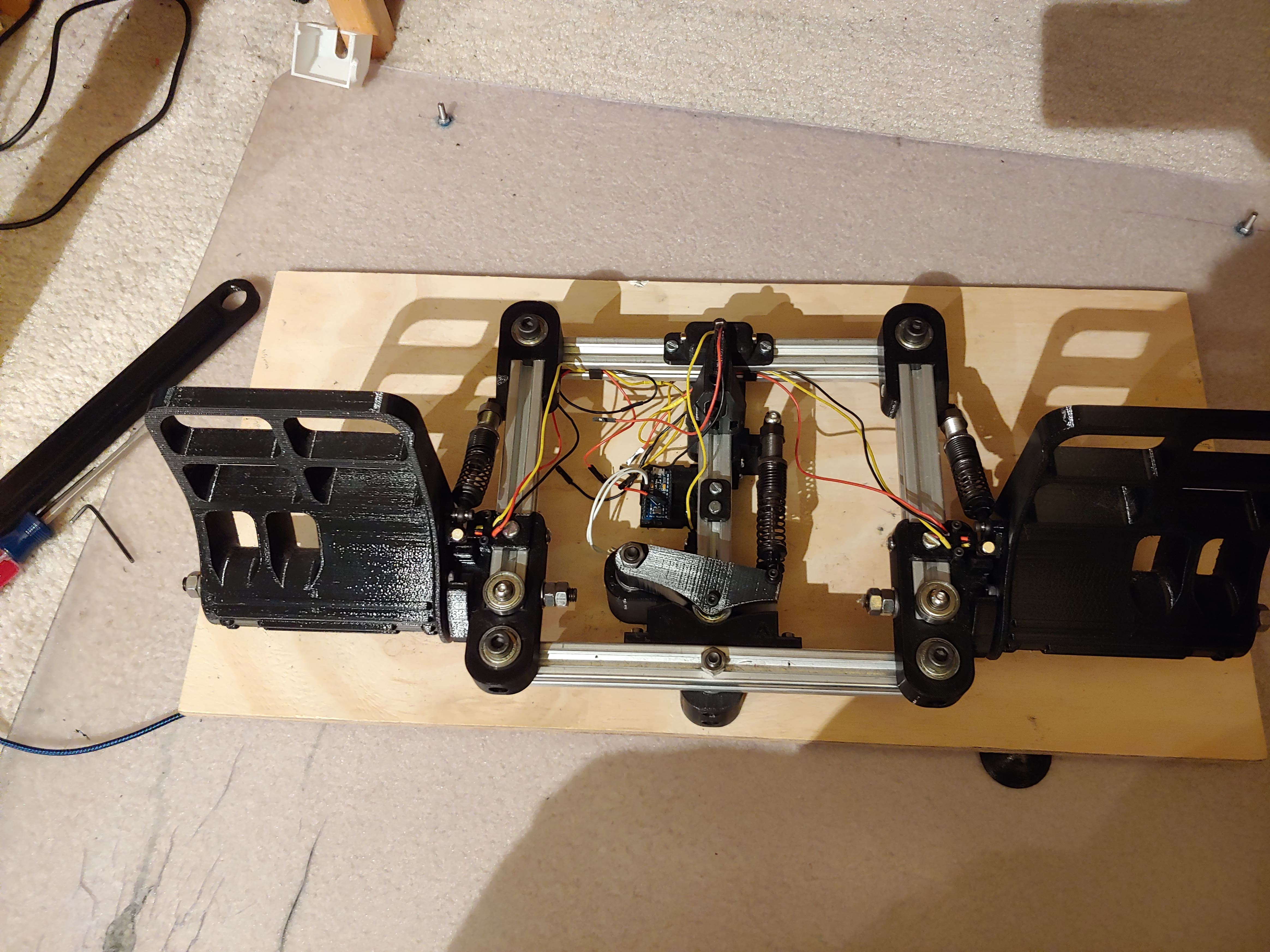
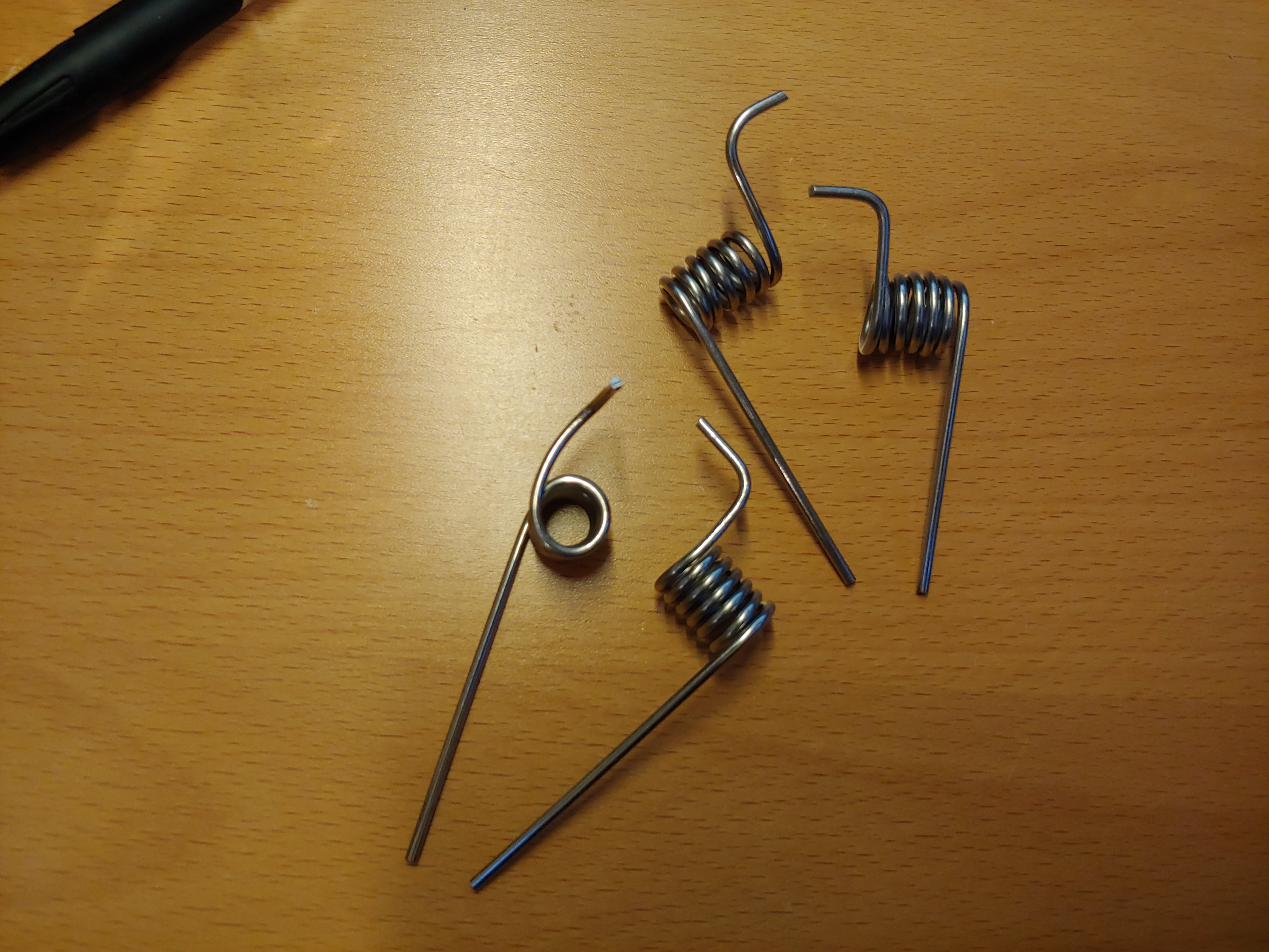
The first version was pretty simple. I just followed the design to the word, using the helpful build instructions PDF and BOM. I ordered the 2020 aluminum extrusion cut to size from ebay, and got a 5mm carbide tip drill bit for drilling M5 holes. I wound my own torsion springs for the toe brakes out of 2mm spring steel rods, as instructed. It did take a few tries, because I was using a very jank setup with a hand clamp instead of a vise.
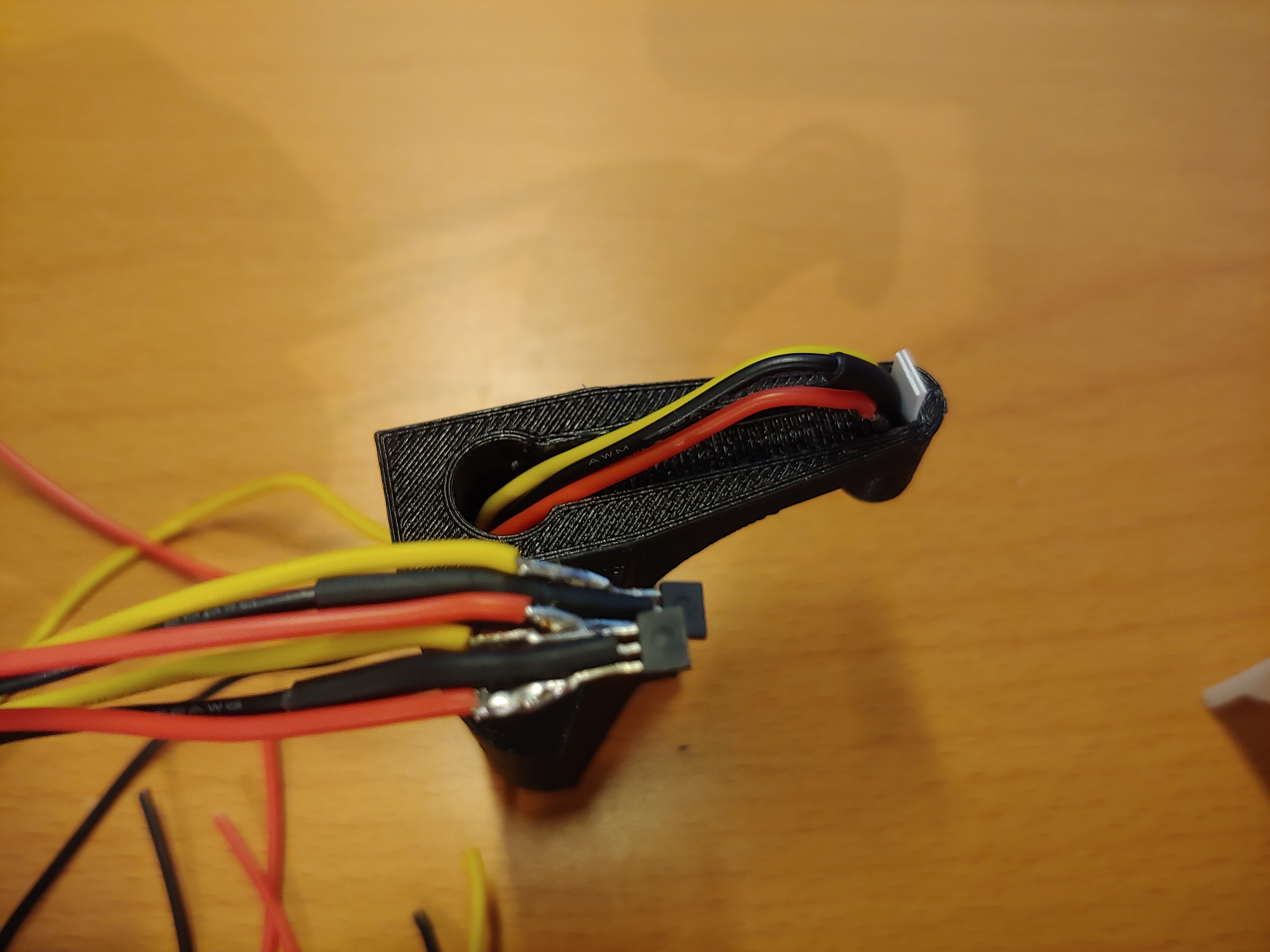
I was also using thicker wire and making thicker solder joints for the hall sensors than the designer did, so I had to do some less-than-ideal heatshrinking.
The build went smoothly and I used the finished pedals for several months before deciding to edit the design.
V2: F-16 Style Pedals
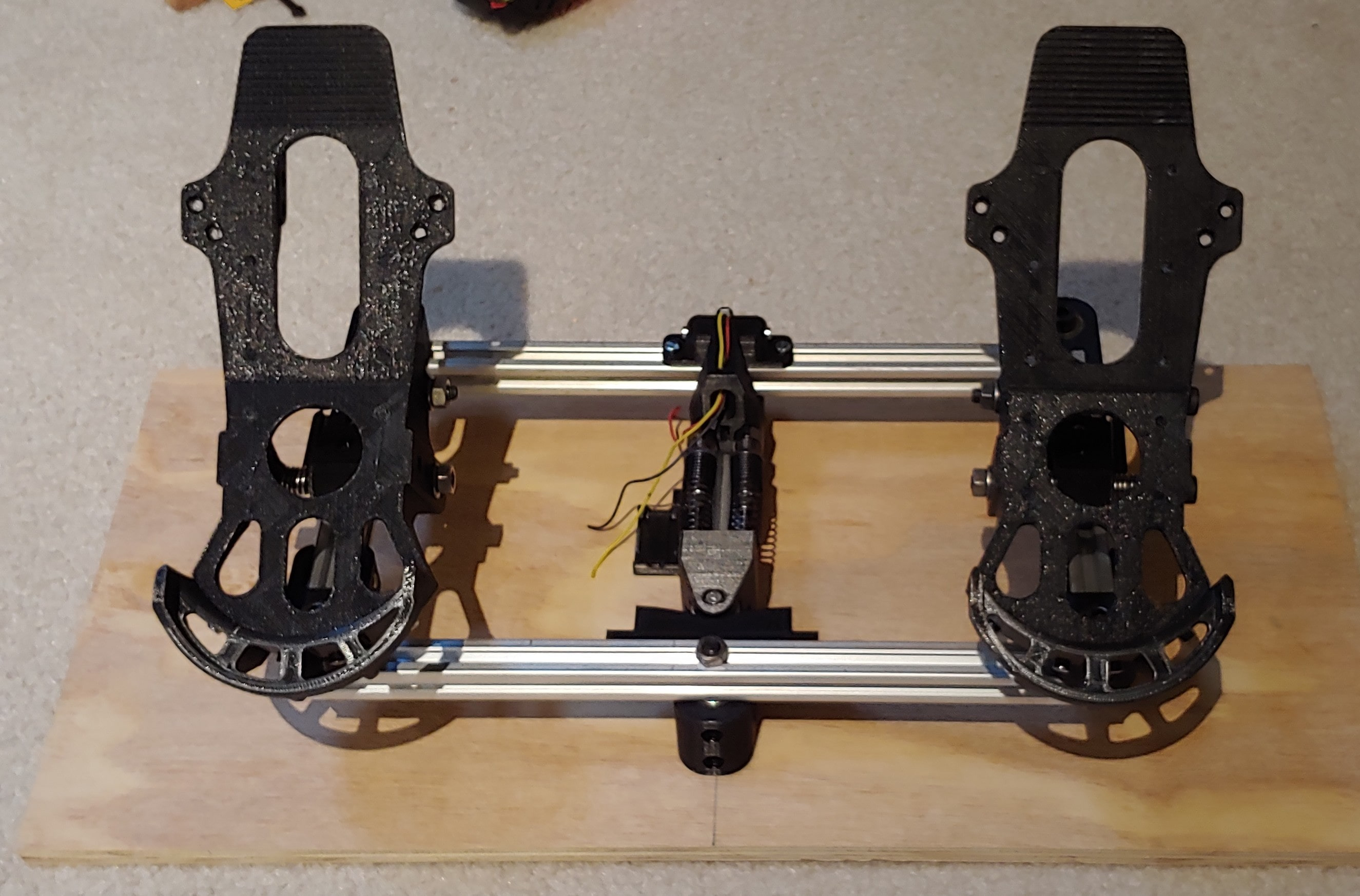
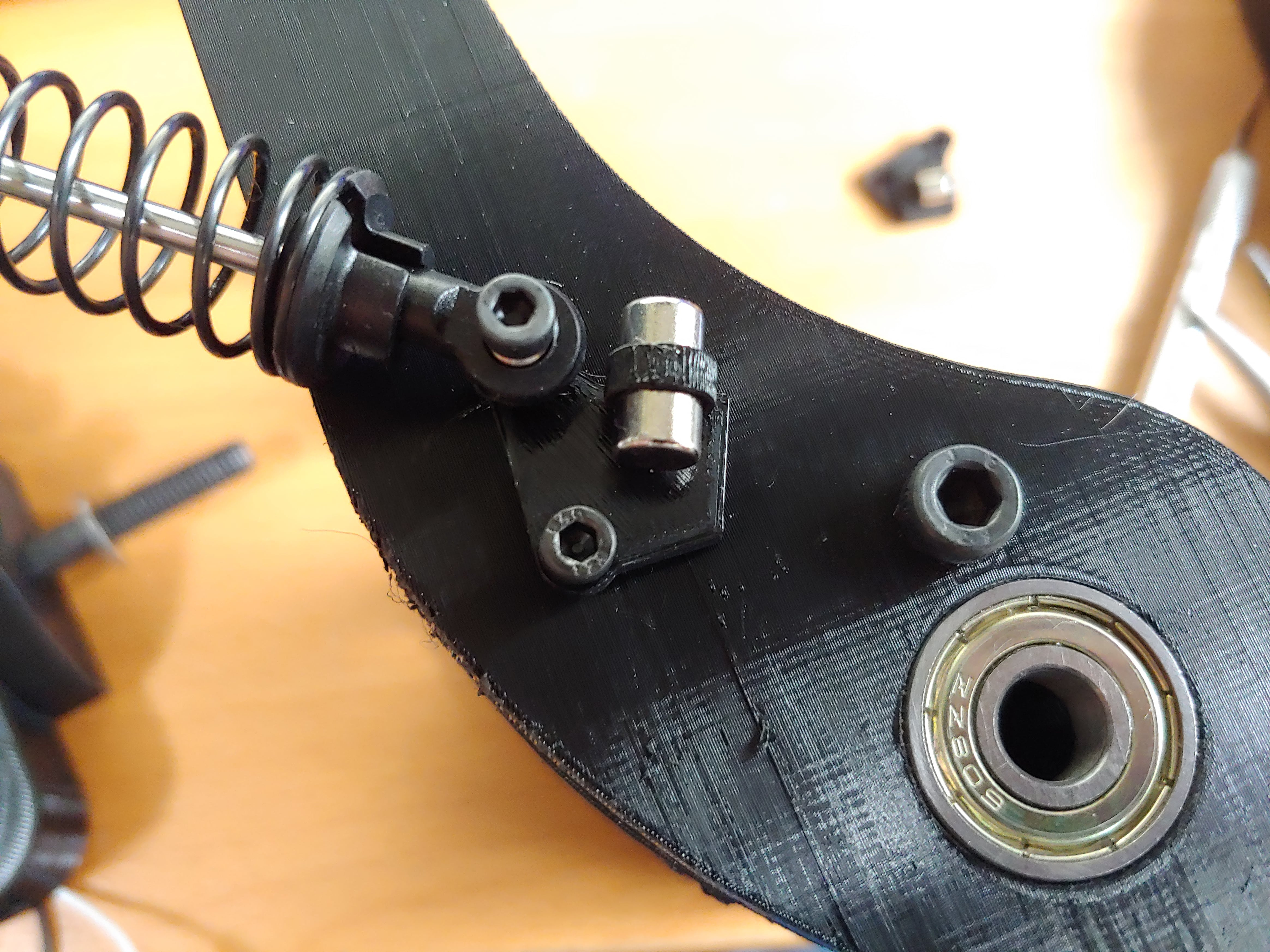
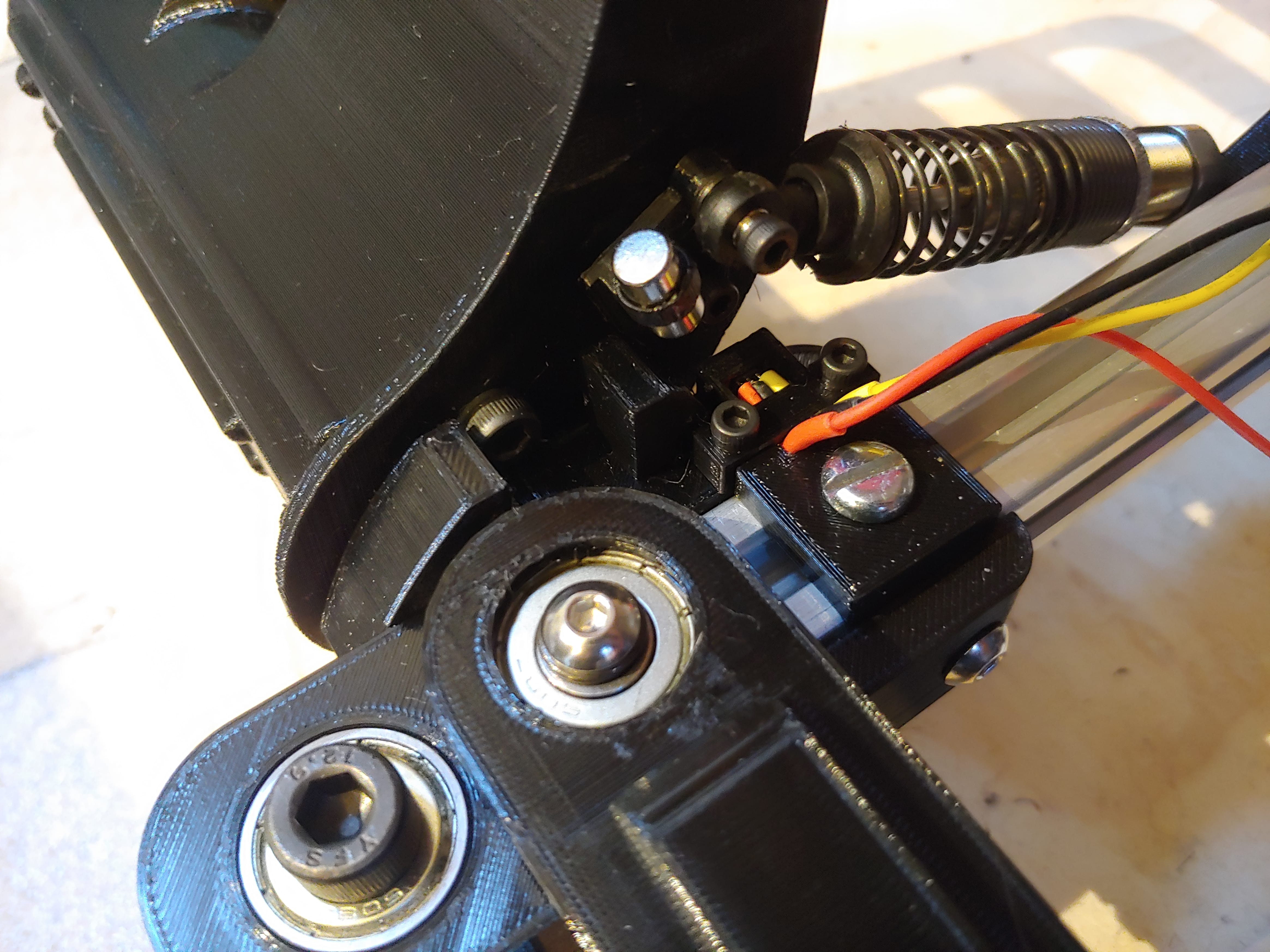
In April ‘21, another member of the HOTAS discord posted a work in progress build of an F-16 style remix of these pedals, and I collaborated with him to design sensor mounts into them. The pedals mechanically required less throw in both the rudder axis and the toebrake axis, making it easier to brake with rudder deflection, and the pedals sat closer to the ground. My sensor mounting solution included strain relief for the hall sensor and a magnet mount on the pedals.
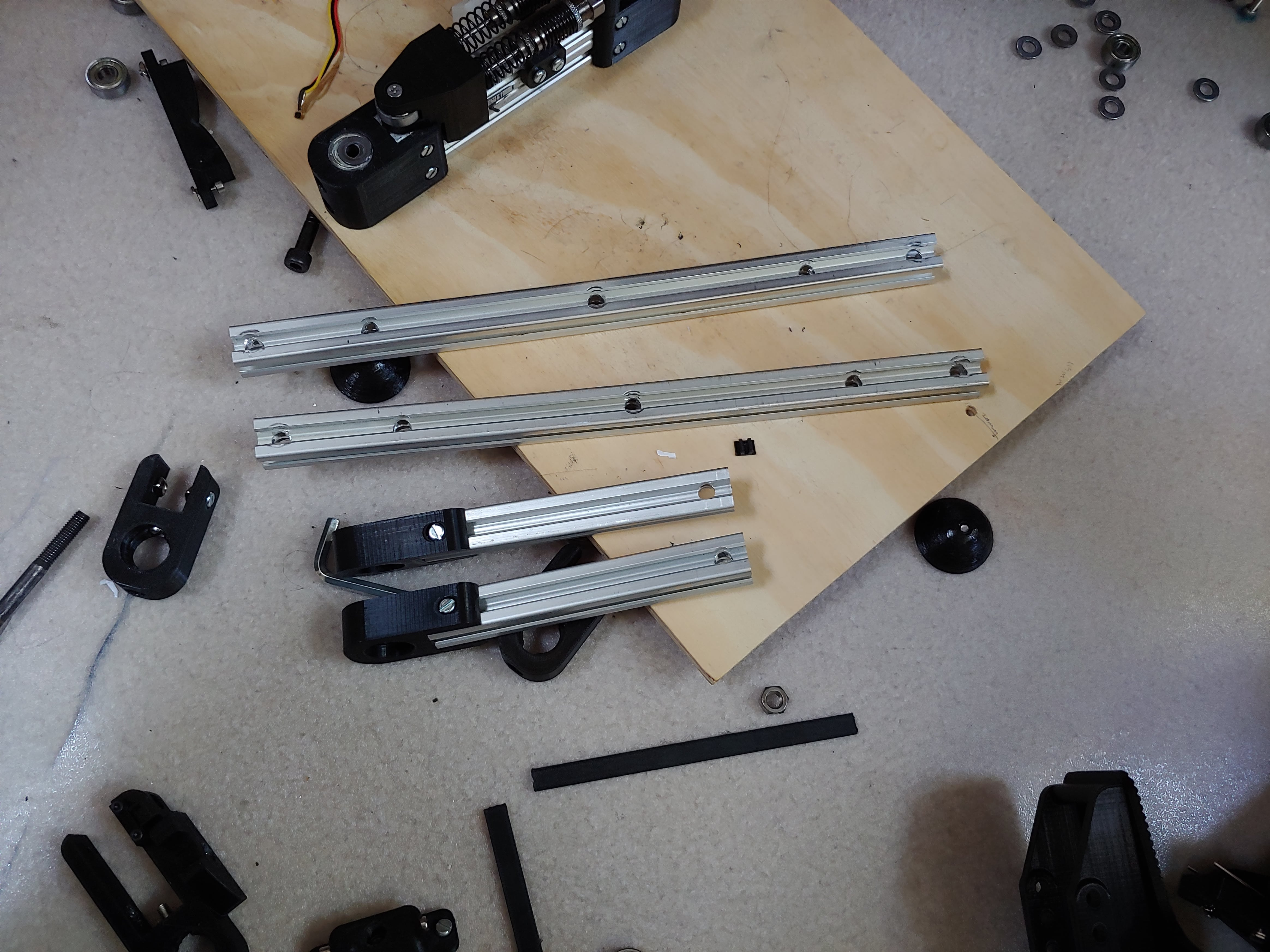
The conversion took a few days, and I had to cut down and drill new holes into the 2020 extrusion crossbars. This time, I could cut on my own because I had a hacksaw from the throttle project.
V3: Asymmetrical Cam Design
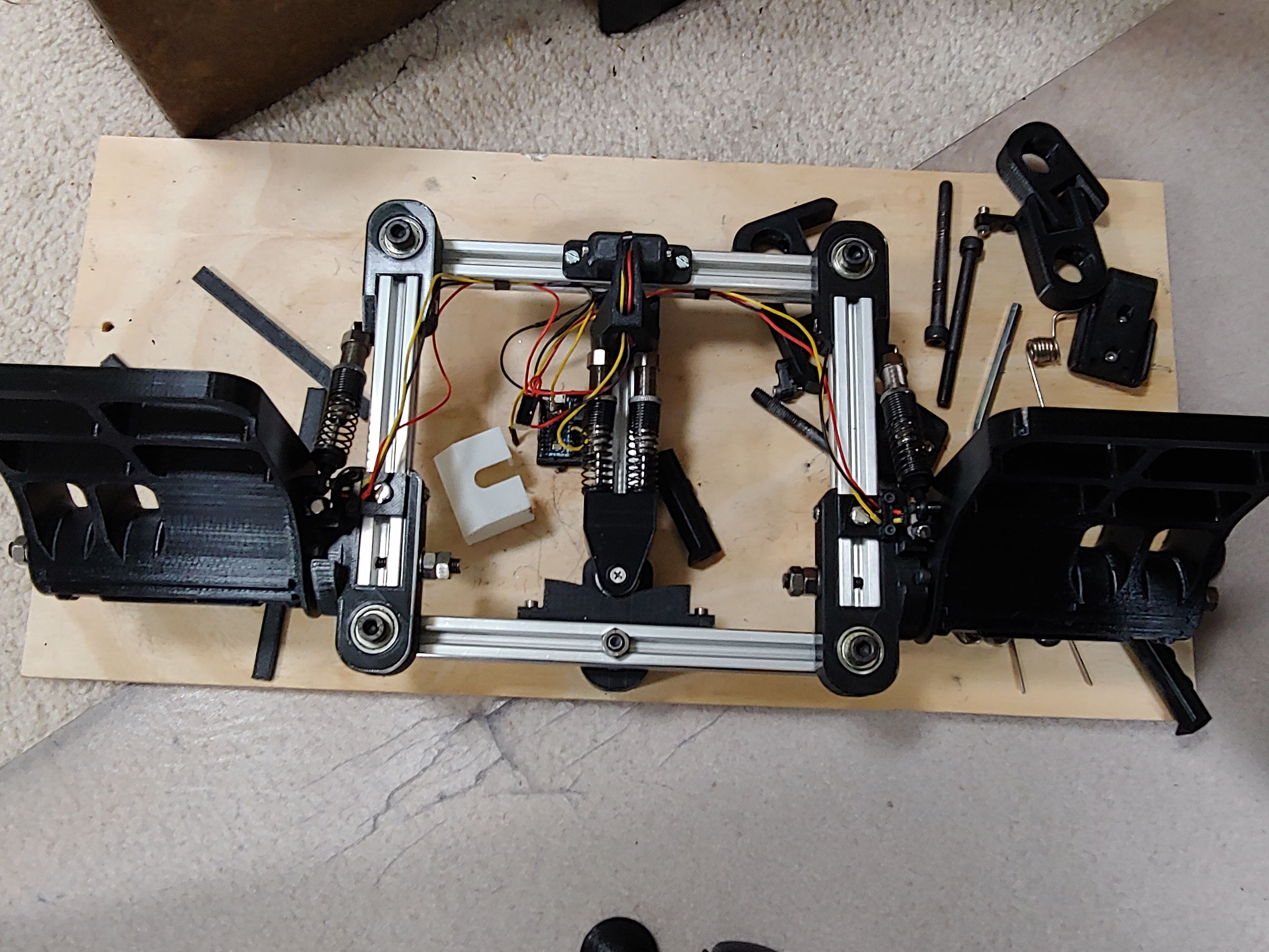
The final modification I made was suggested by that HOTAS discord member. The original design uses a 3D printed part that slides against the aluminum extrusion and pushes against a symmetrical cam for centering with two linearly actuated RC shocks.
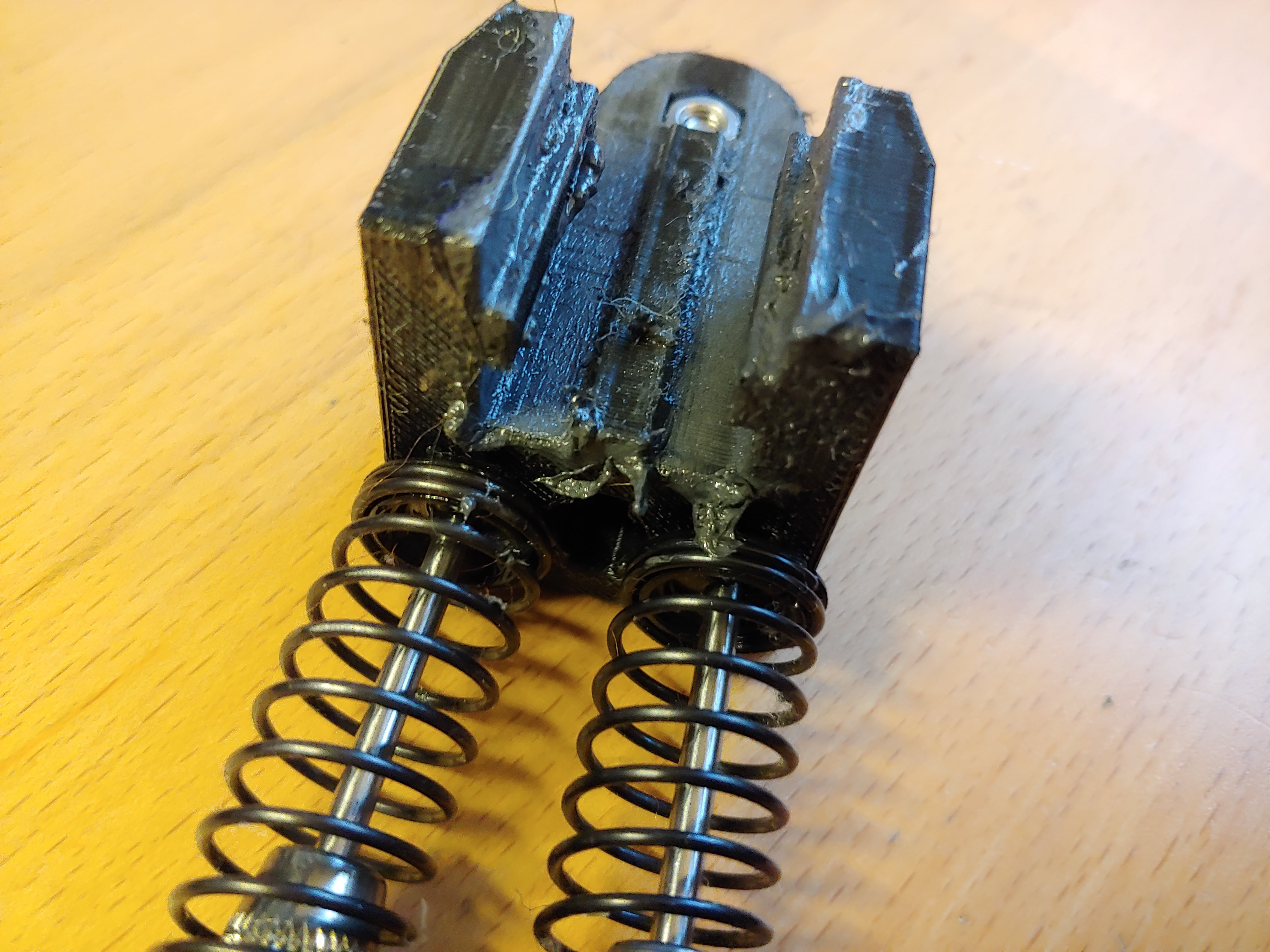
Besides getting very dirty, the slider also wears down and generates friction. So a better design would use an asymmetrical cam centering system, similar to the MFG Crosswind rudder pedals. Instead of having a linear slider, the roller would be mounted to a pivot pressed against the cam on one end by the RC shocks, forming a simple lever. This would require an asymmetrical cam geometry, so that the deflection of the spring is equal at equal deflections in each direction. One way to do this would be a much of MechE math I didn’t know at the time, but I chose to just trace each cam position at each deflection angle in each direction to form a guide for a spline in Fusion 360. It took a couple hours, but it worked.