This was one absolute monster of a project, taking five months from my first CAD at the end of November ‘20 to my final code edits in May ‘21. This remains my proudest flight sim gear project, and it really would not have been possible were it not for the pandemic and online school.
If this is v2, where is v1?
I designed my first throttle in the summer of ‘20. It was a simple tabletop design with CNC rails and an arm connected to a hall sensor, similar to the Thrustmaster TWCS throttle. The design was a bit clunky, had a lot of axis nonlinearity because of the sensor arm, and had issues with the rails sticking because I didn’t use linear bearings.
Initial Design
I started playing around with the idea of a desk mounted throttle instead of a tabletop design towards the end of my Viper stick project. I wanted a long throw throttle with about 200mm or more of travel for greater resolution, but I also wanted rotating arms rather than a linear sliding throttle to give tactile position feedback (in other words, being able to tell where the throttle physically is without having to look at it).
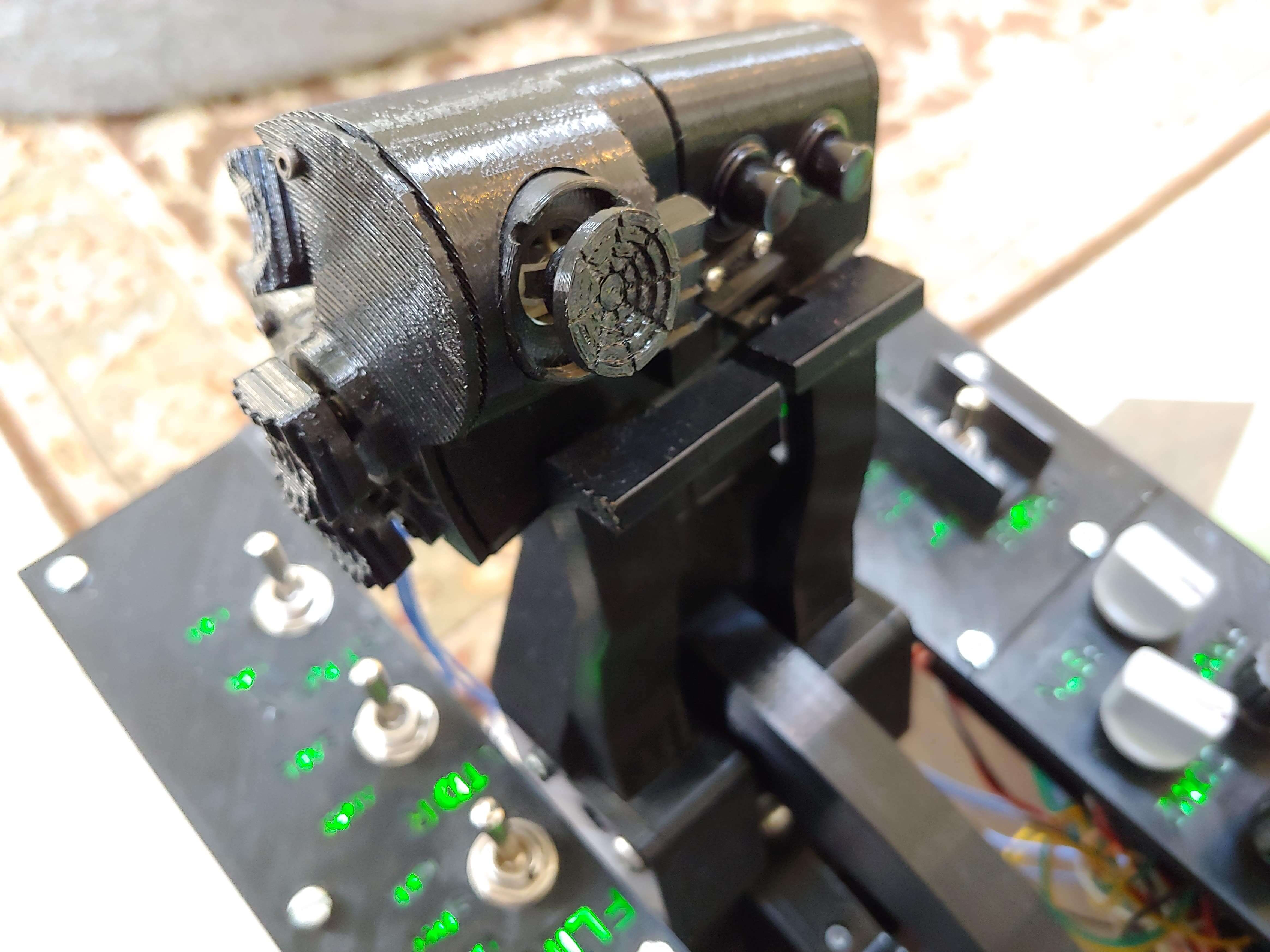
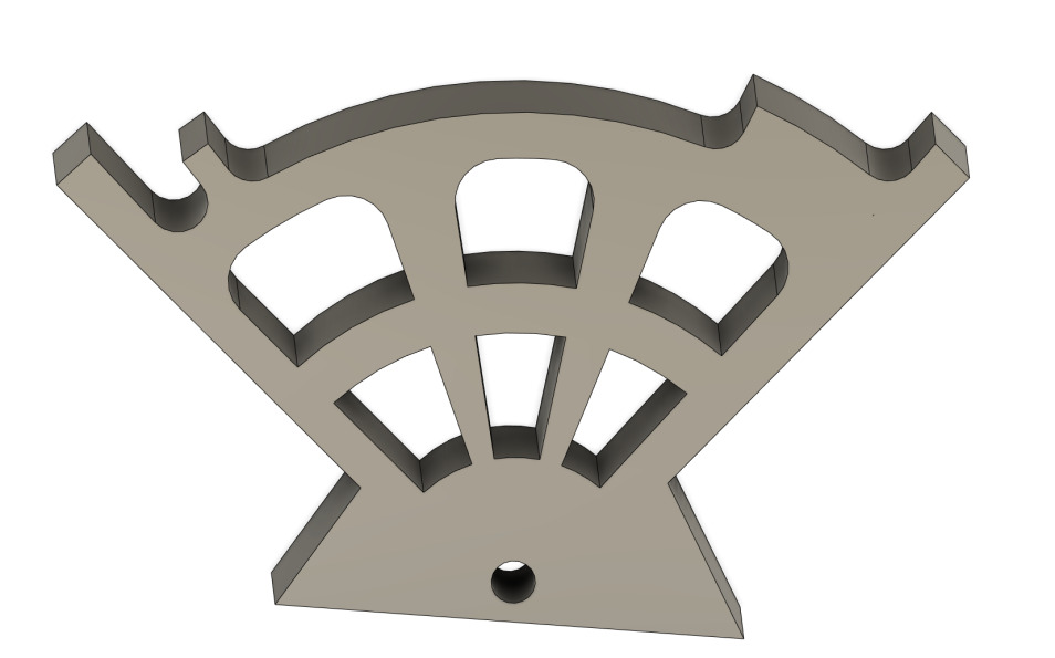
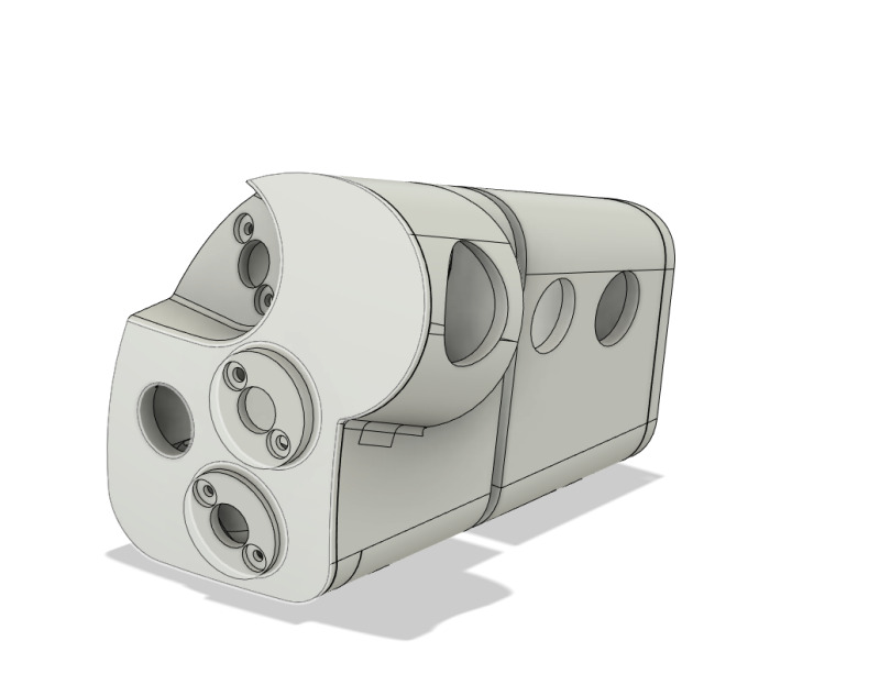
I started with the detent track, which is basically a large cam that the two fingerlifts press against, giving tactile feedback for transitions between off, idle, normal flight, and afterburner.
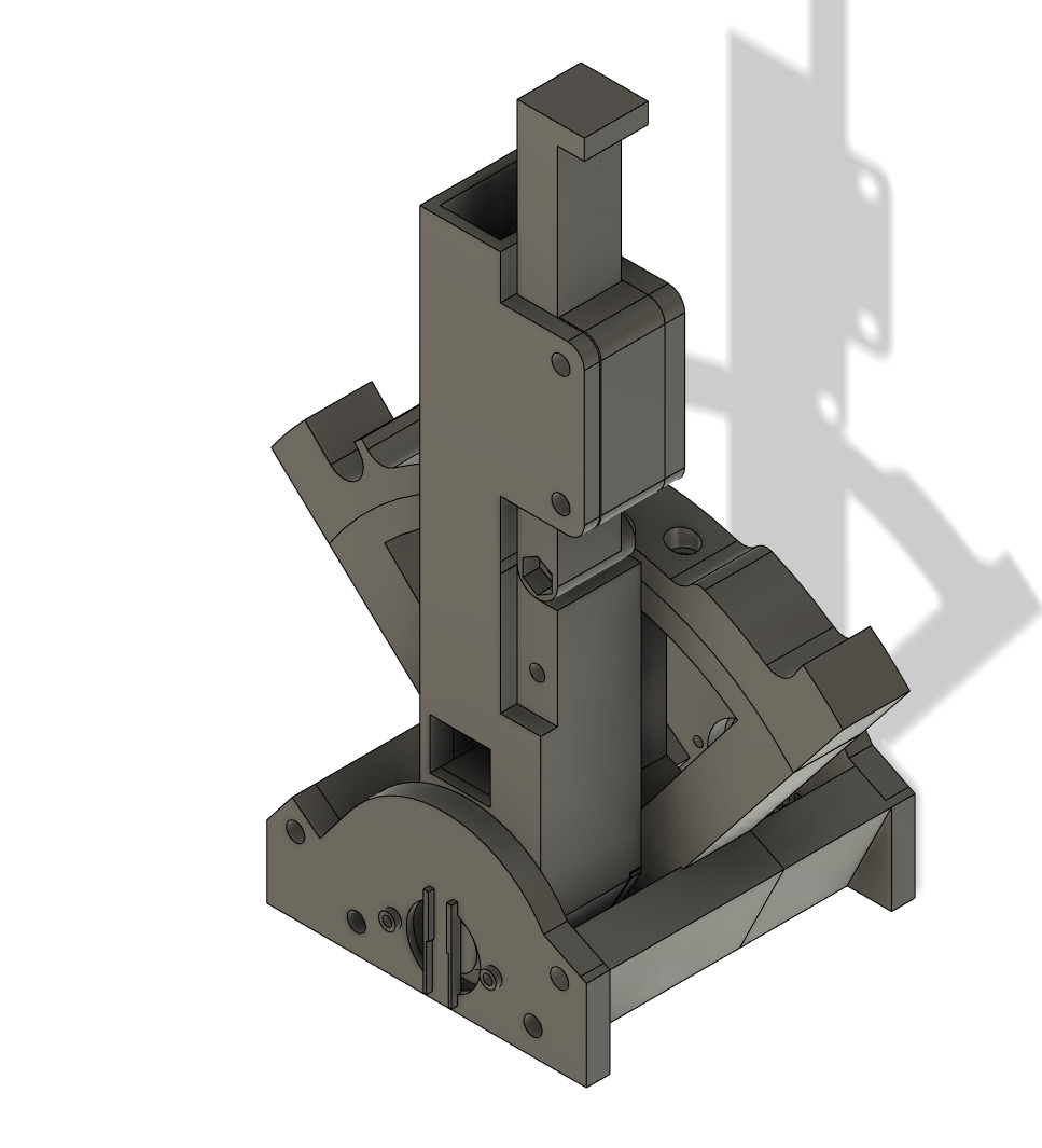
Just a few days later, I finished up the assembly for the throttle arms and detent track.
The next week, I got to work on the grip. Since I still couldn’t design anything ergonomic, I found a design by olukelo and adapted it to my needs. I wanted more of an F-18 style grip, and I wanted it to split for individual engine control.
Prototyping
I printed out a prototype of the detent mechanism, with a representative arm and fingerlift design. I used some red filament because I knew I was going to have to reprint a new version anyways. I posted a video testing out the mechanism. The fingerlifts used extension springs hooked on screws to tension the arms against the detent track.
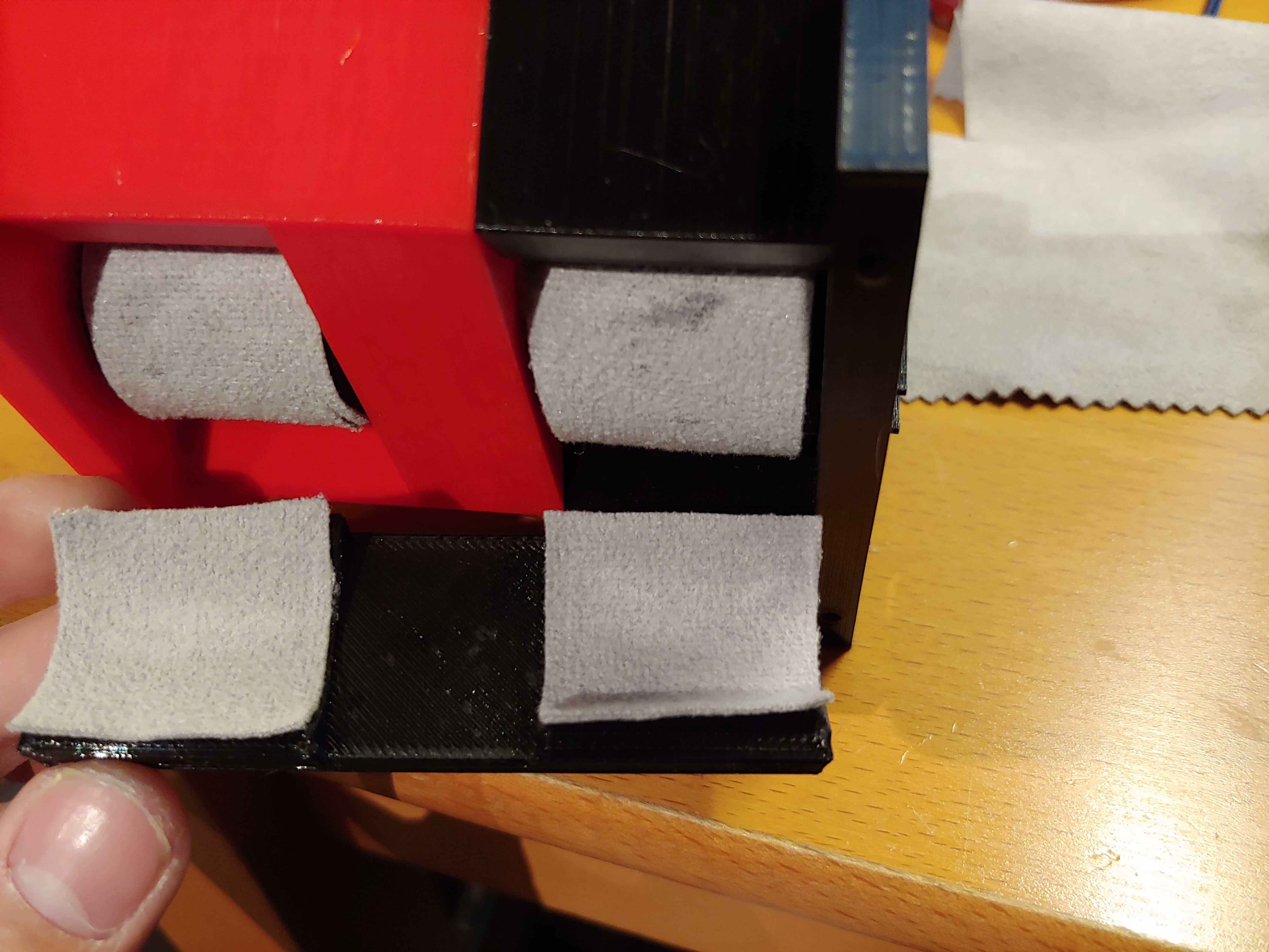
I moved on to designing a mechanism to provide friction, and I decided use felt pads glued to the bottoms of the arms and a plate underneath pressed up against the arms with two M5 screws. I posted another video.
I designed in endstop switches for the off/idle detent, so that I could bind the movement of the throttle arms over this detent to idle or shut down the engines in game.

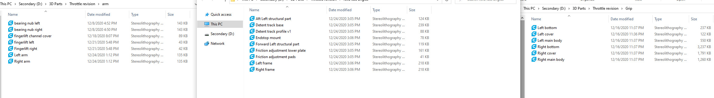
After testing these mechanisms on their own, I finished up the CAD of the entire arm assembly, from base to grip, and got to work printing them out. Among the major changes were fingerlifts that extended all the way to the grip, and adapter prints to mount the grips to the arms. I also designed channels into the arms for wiring to run through. I decided to copy over the sensor mounting solution I came up with for my Viper stick, since it worked fine and could be applied to this just as well.
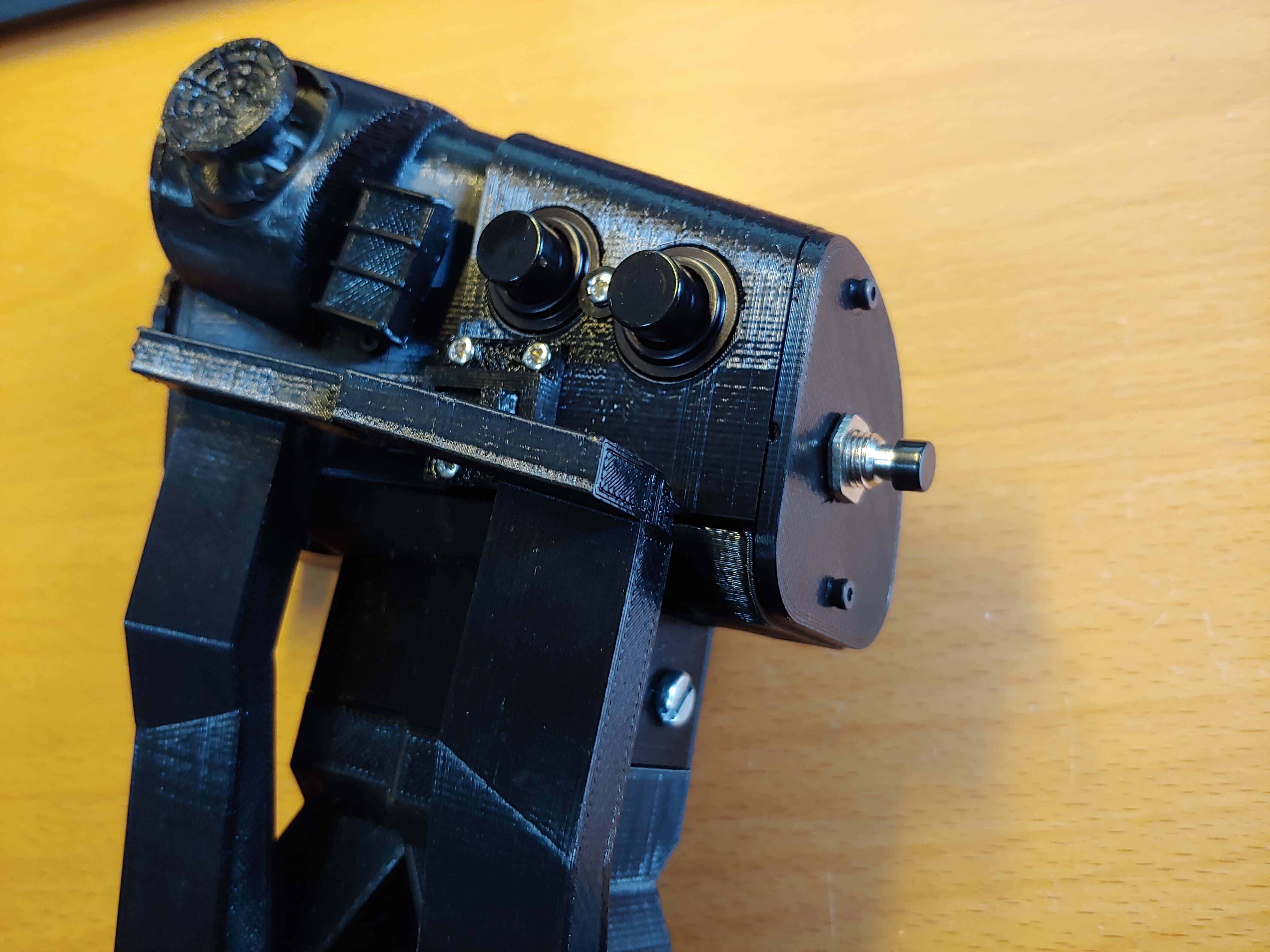
I also made a few edits to the grip. I decided to splurge on a couple milspec Otto P1 pushbuttons for the left grip half. They costed $18 a piece but they are the most satisfying pushbuttons in my posession, with an actuation force of 2.5lbs. I also designed a sliding latch for the two grip halves, so that I could move them both as one if I didn’t need separate engine control.
PCBs
Just like the Viper stick, I needed shift registers for the right grip, since there would be three hat switches and several other button inputs, totalling 19 inputs. Running 20 wires through the arm was out of the question, and shift registers would allow me to run just five.
It was clear that perfboard wouldnt fit inside the grip this time, unlike what I could get away with on the Viper stick, and I wanted to use an Alps RKJXV thumb stick instead of generic Arduino thumbsticks that come on breakout boards, since the RKJXV has no deadzone in the center. I got to work designing two PCBs, one to hold three shift registers and that would fit inside the grip, and another to mount the RKJXV thumbstick.
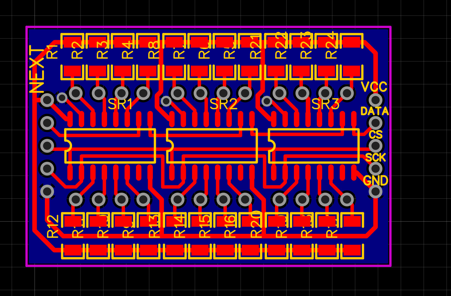
These were the first PCBs I ever designed and ordered, and I designed both without even designing a schematic first, but it ended up working out since they were so simple. The shift register boards were simply three daisy chained 74HC165s with pullups on their parallel inputs.
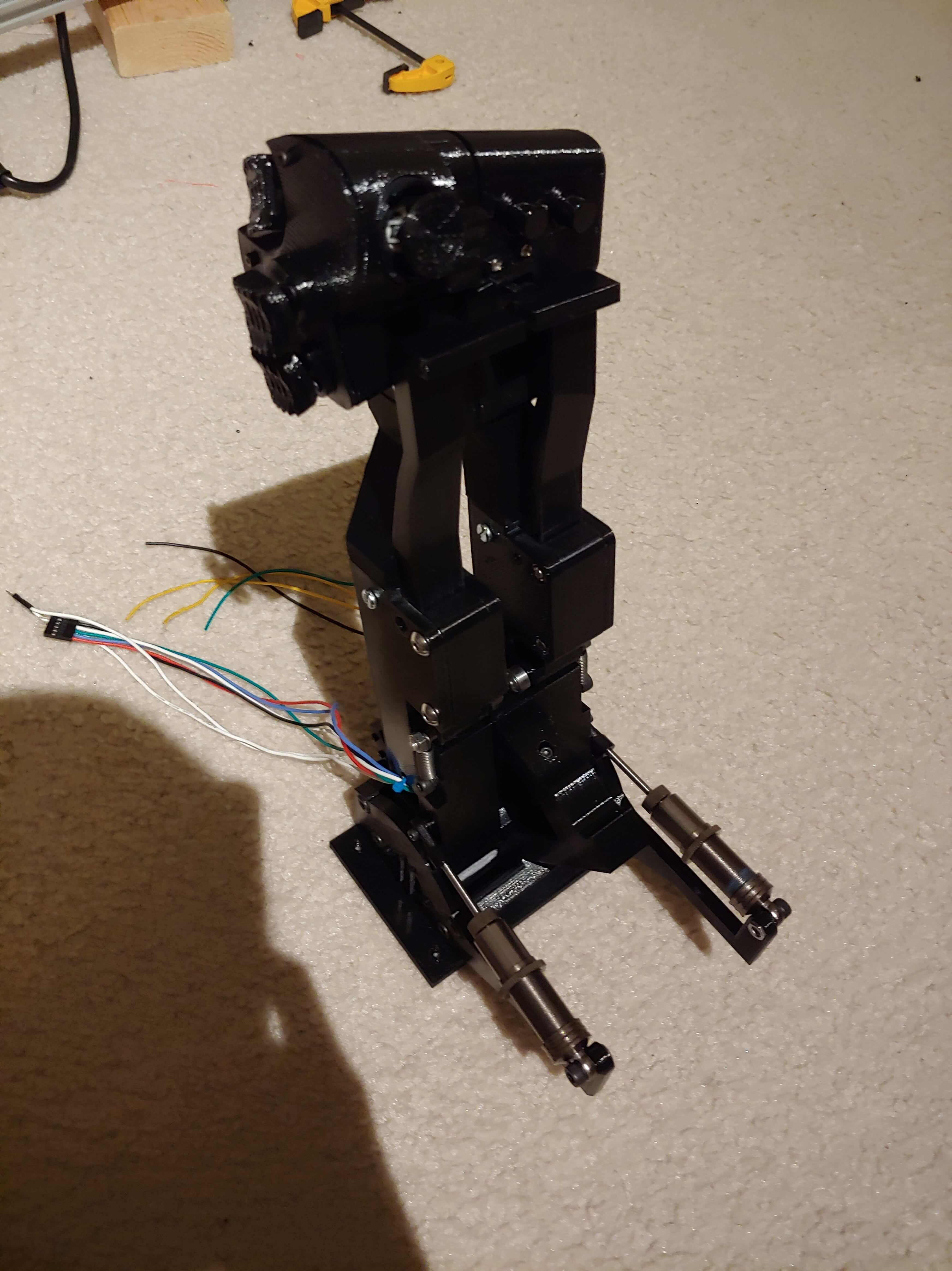
Assembly
By January, I had all the parts printed, and I started assembling
I started wiring inside the grip, using the same ethernet wires as I did on my Viper stick project since it was a tight squeeze (even more so than before). I had made the critical mistake of not putting ground connections on the shift register PCBs, which made wiring much harder since I had to “steal” ground from the shift register input connection for the buttons. I finished up the grip and tested it with MMJoy2.
After finishing the arm assembly, I posted yet another video
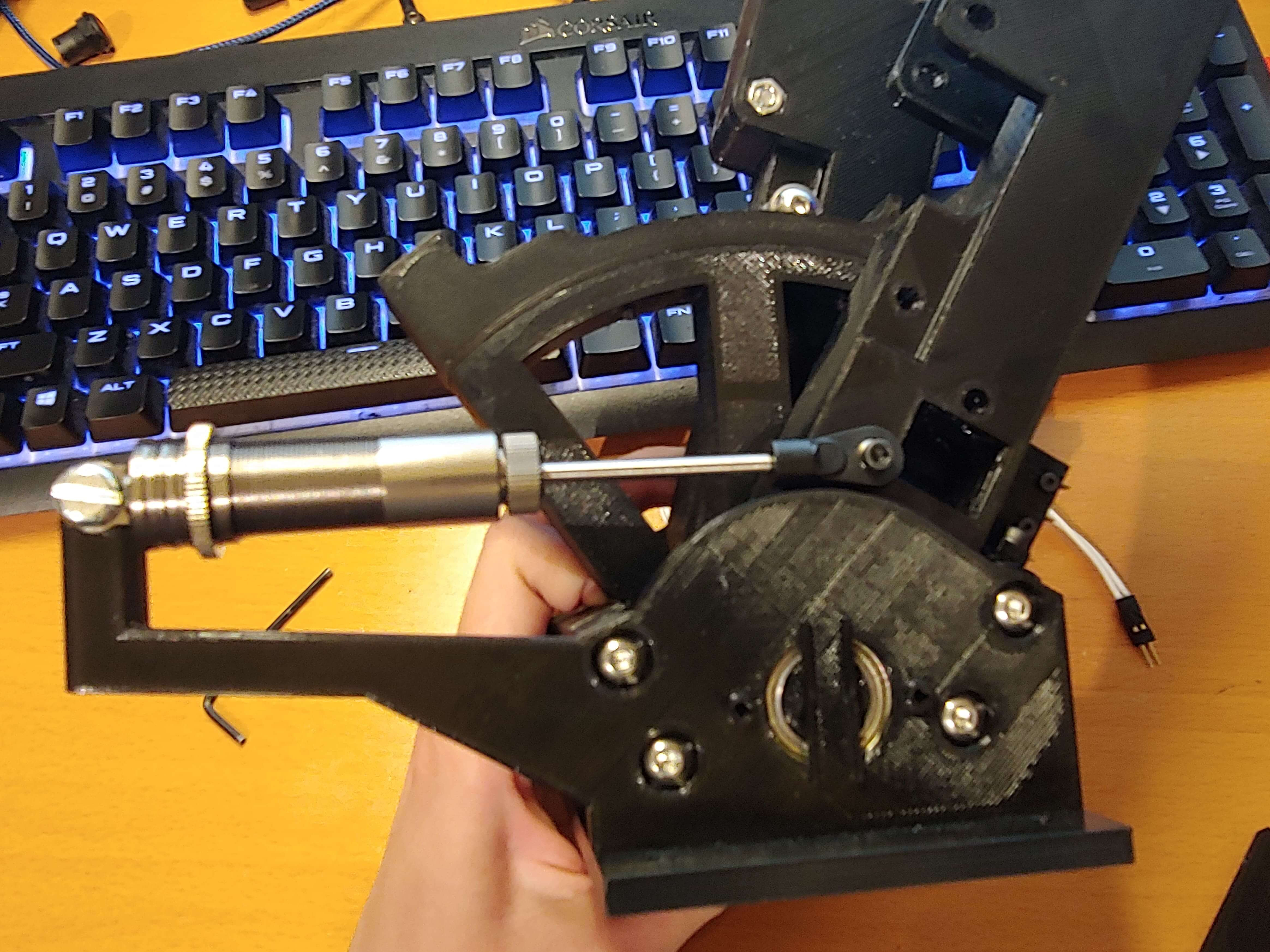
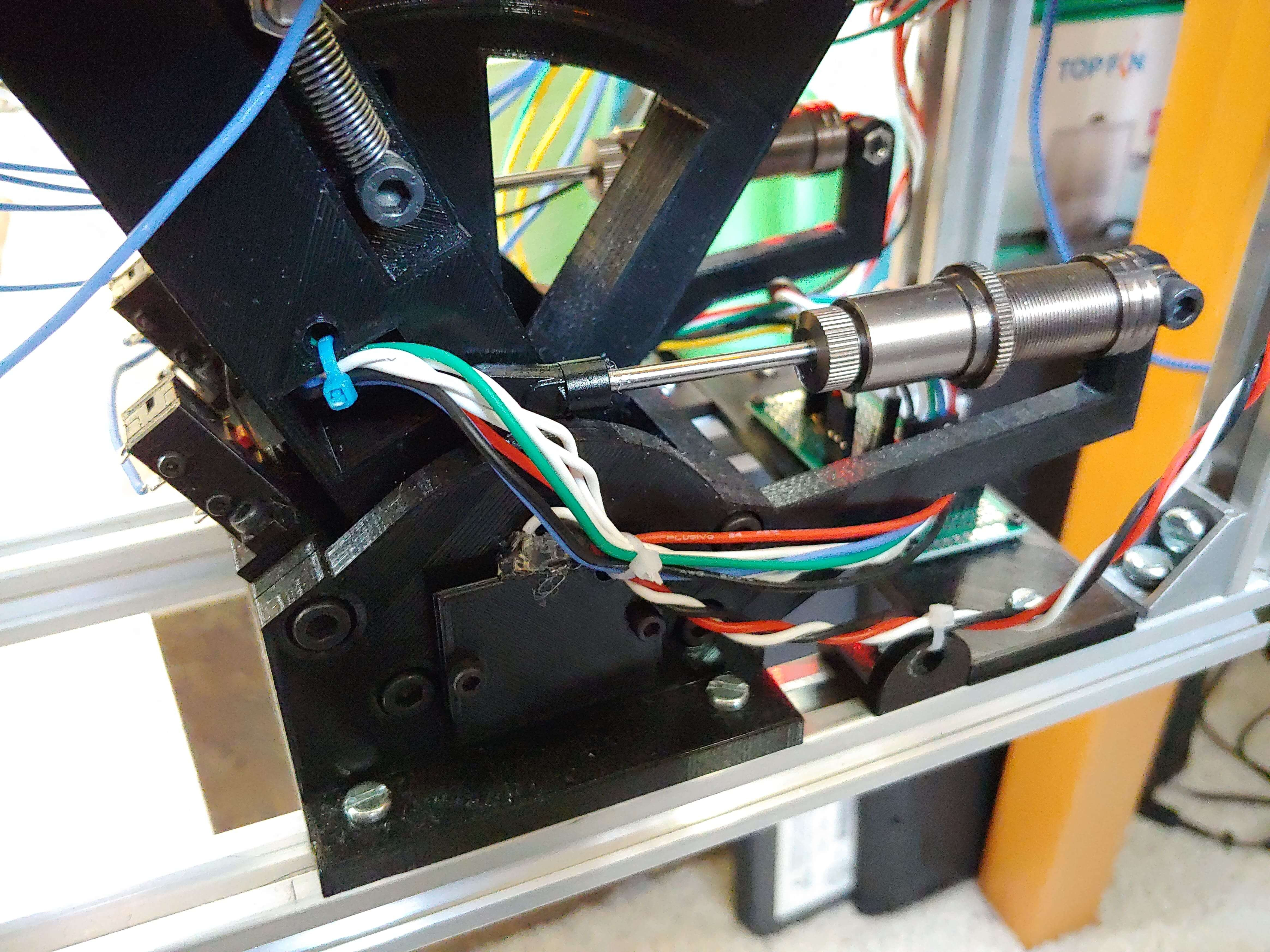
I realized that the felt friction mechanism wasn’t giving the right feel, even after I applied nyogel 767a to it. I decided to use RC shocks for further damping. I bought some 130mm RC shocks, removed the springs, and filled them with 50 weight shock oil. I had to redesign and reprint the arms and frame pieces to mount them.
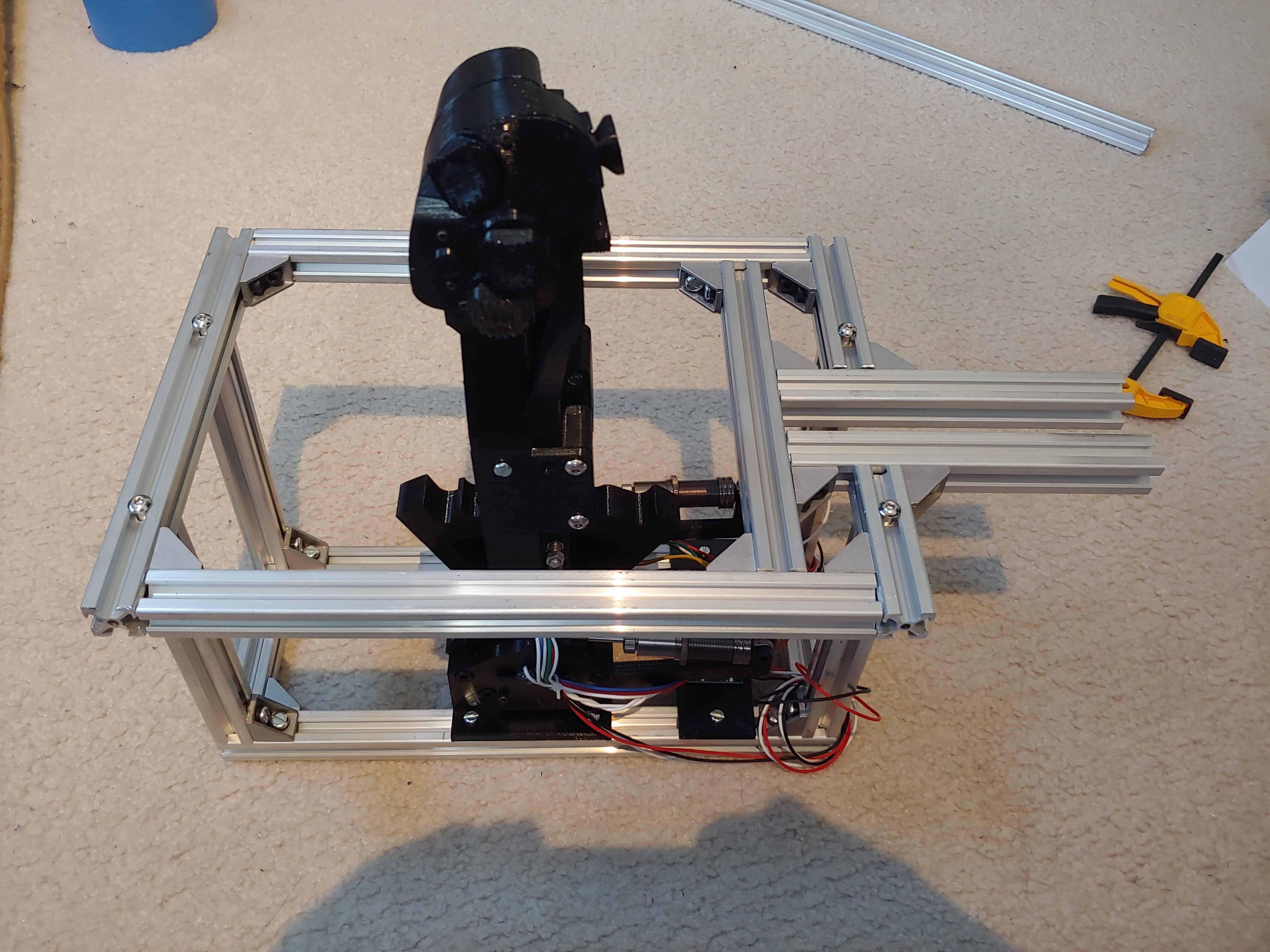
Frame
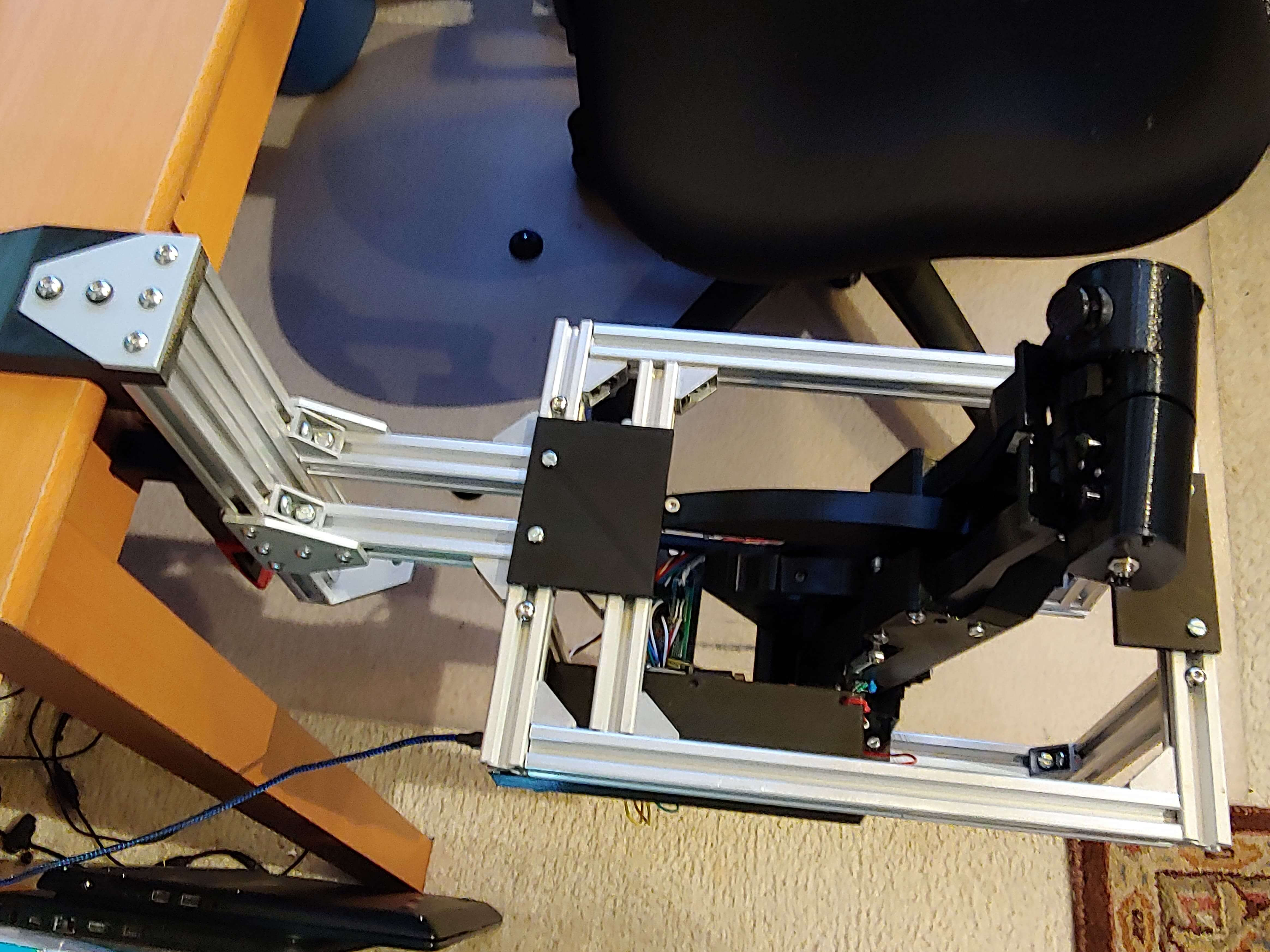
I now had to design the frame, which would mount the assembly to my desk and mount beauty panels and switch panels. I used 2020 extrusion, since prints could be easily mounted to it with T nuts. I drilled 5mm holes and used M5 bolts, T nuts, and L brackets to fasten the frame extrusions together.
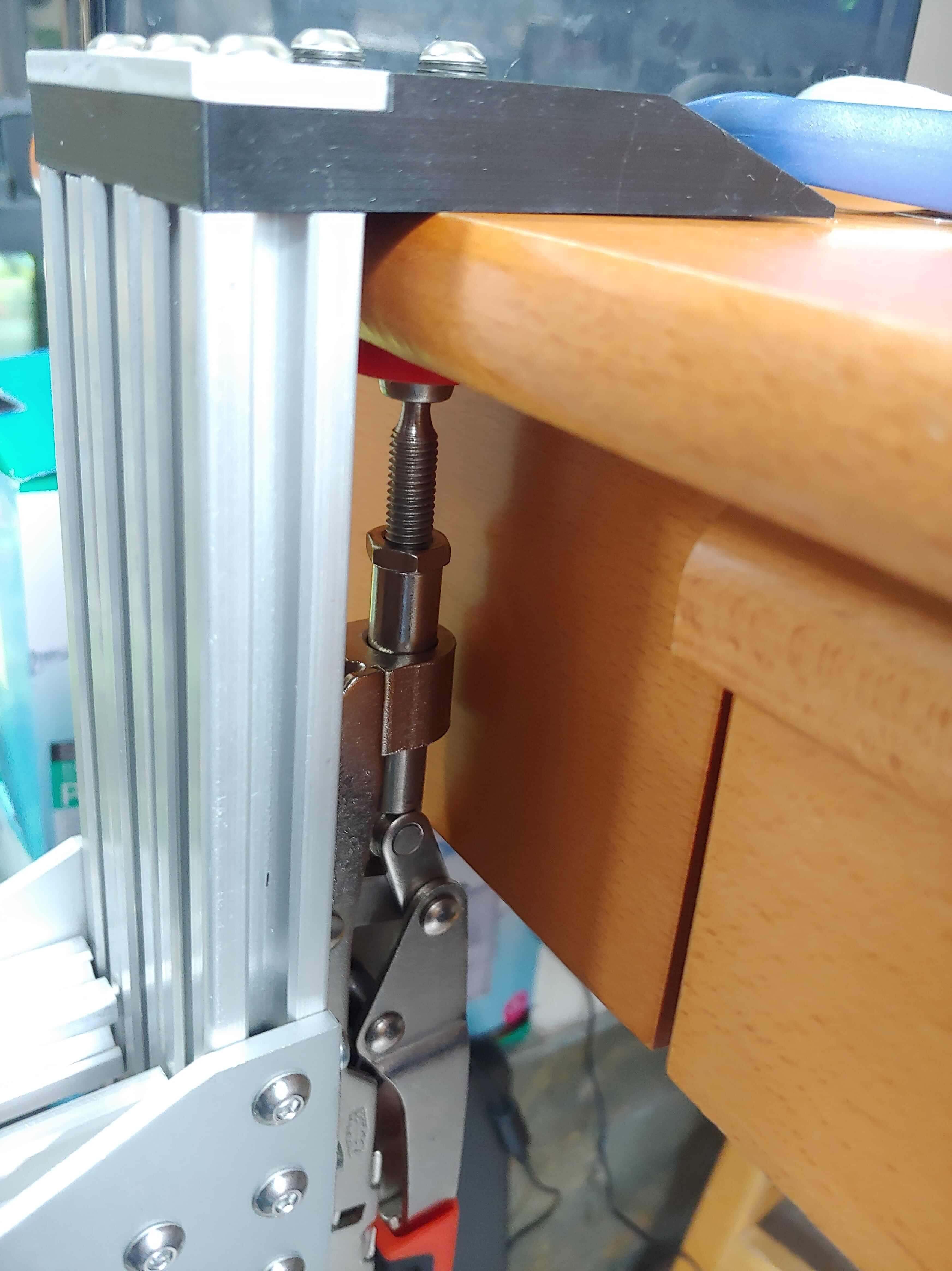
To mount to my desk, I used the same Bessey clamp that Monstertech uses, but I printed a longer clamp top piece since my desk has a drawer underneath that keeps the clamp from being placed far back enough.
Electronics
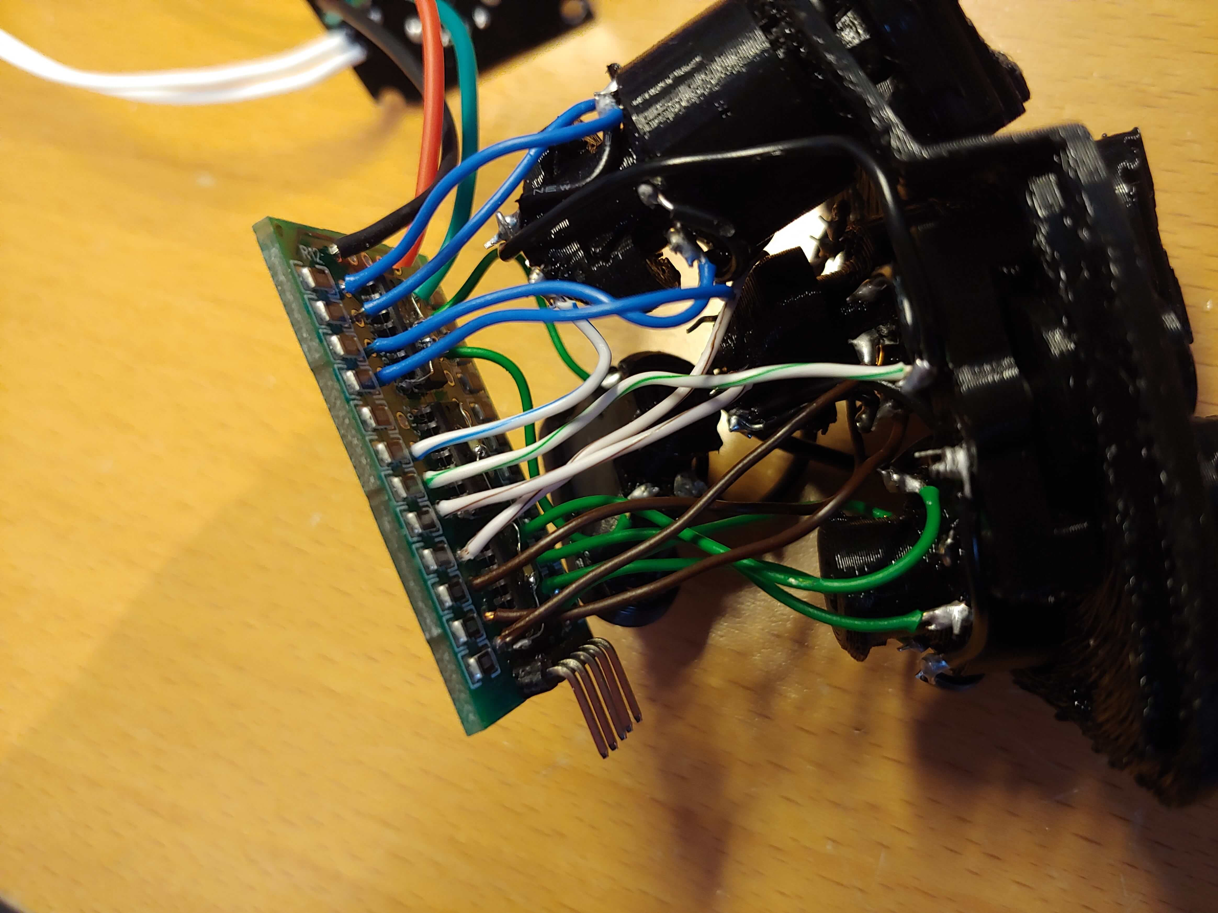
Around the same time that I was designing the frame, I started wiring. I assembled a similar mainboard to the Viper stick project, with an MCP3208 ADC and connections for shift register from an Arduino Pro Micro.
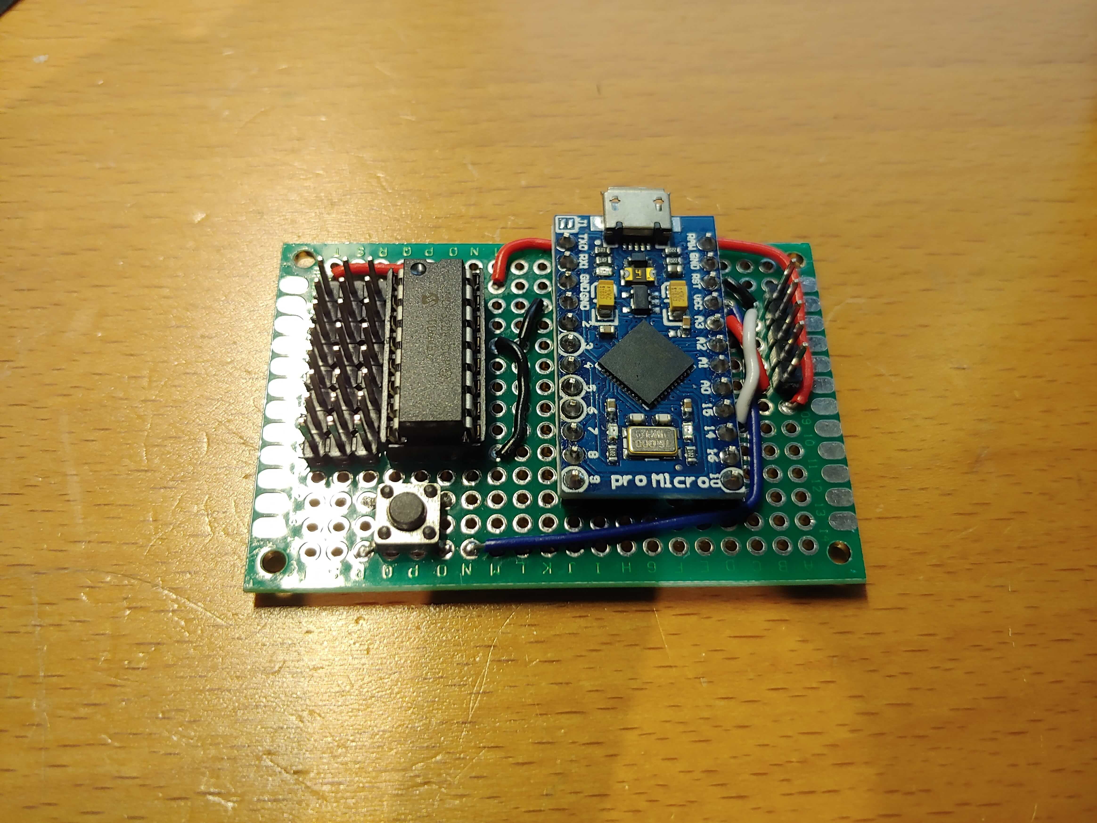
I printed a couple parts for holding perfboard and PCBs, which mounted in front of the arm assembly and on the left side of the frame. I worked through cable management, with zip ties and printed tie down points that mounted on the extrusion. I daisy chained two more shift register boards between the Arduino and the grip for beauty panel switches, and the buttons on the left side grip.
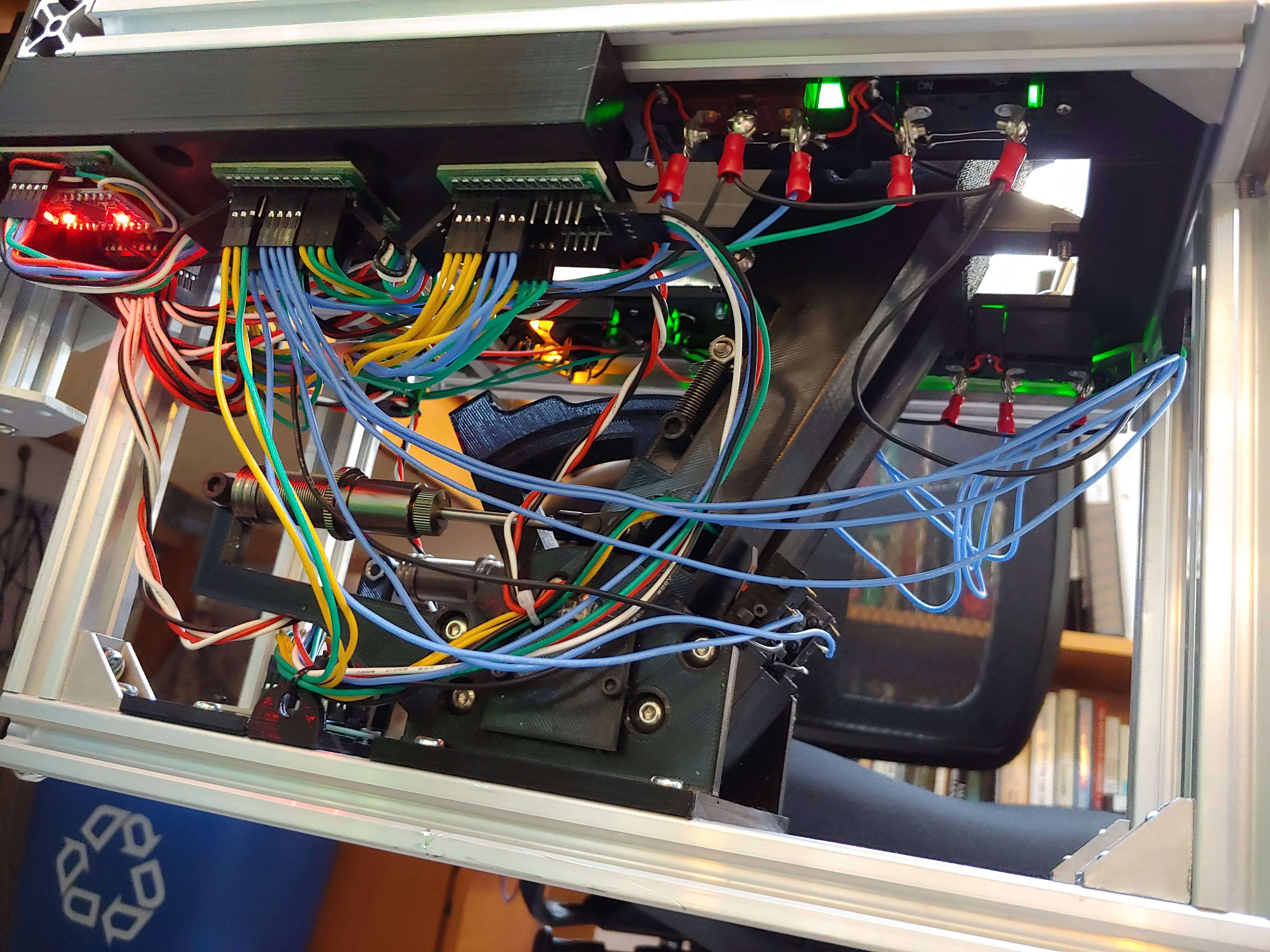
It’s a rats nest, and I have gotten significantly better at wire management since then.
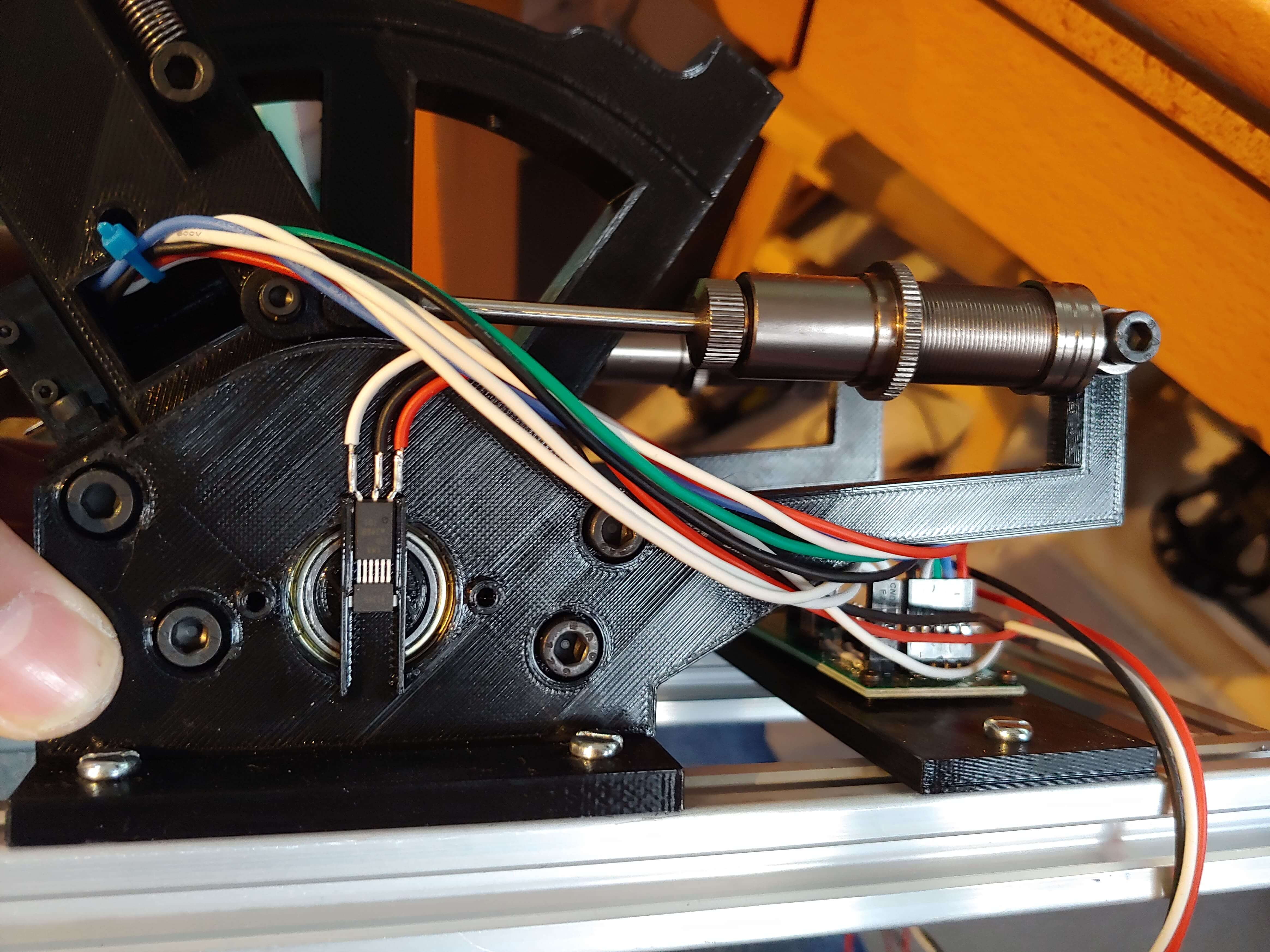
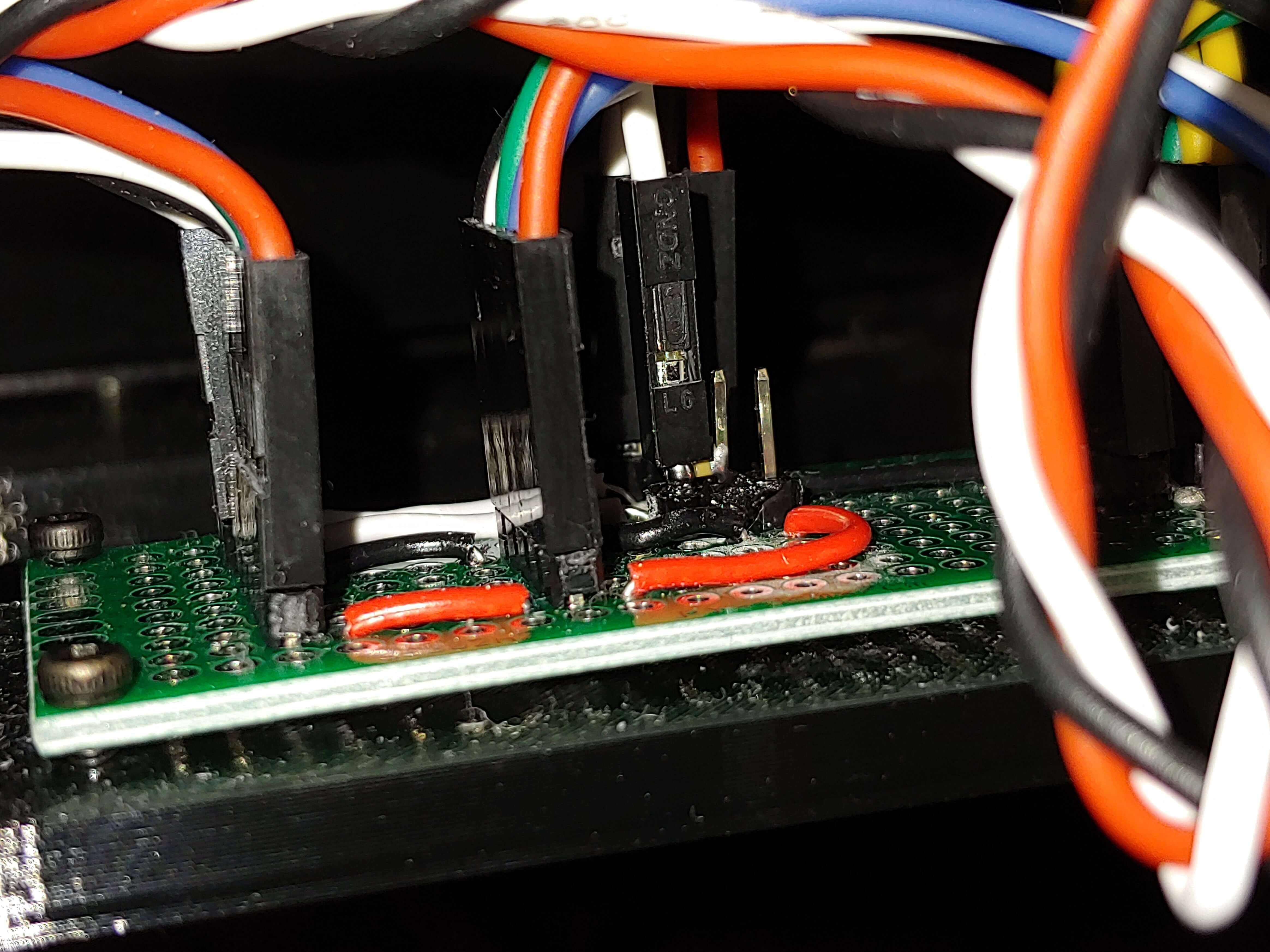
I ran into an issue with the fingerstick axes having too much noise, which was because the analog signal wire ran 300mm and wasn’t routed well to reduce noise. The proper solution would have been to improve routing or reduce noise with a differential or digital signal, but I decided to just filter out the noise with a 0.1uF capacitor on the line. I soldered an 0603 cap between the two header pins on the perfboard.
I also broke a hat switch off the grip and broke the lower gip print, and had to take the grip apart to fix it, but I had previously placed the connector for the fingerstick inside the grip making it impossible to replace the lower print without breaking the wire. I broke the wire and added in a second connector accessible from the outside of the grip just in case I would need to do something similar in the future.
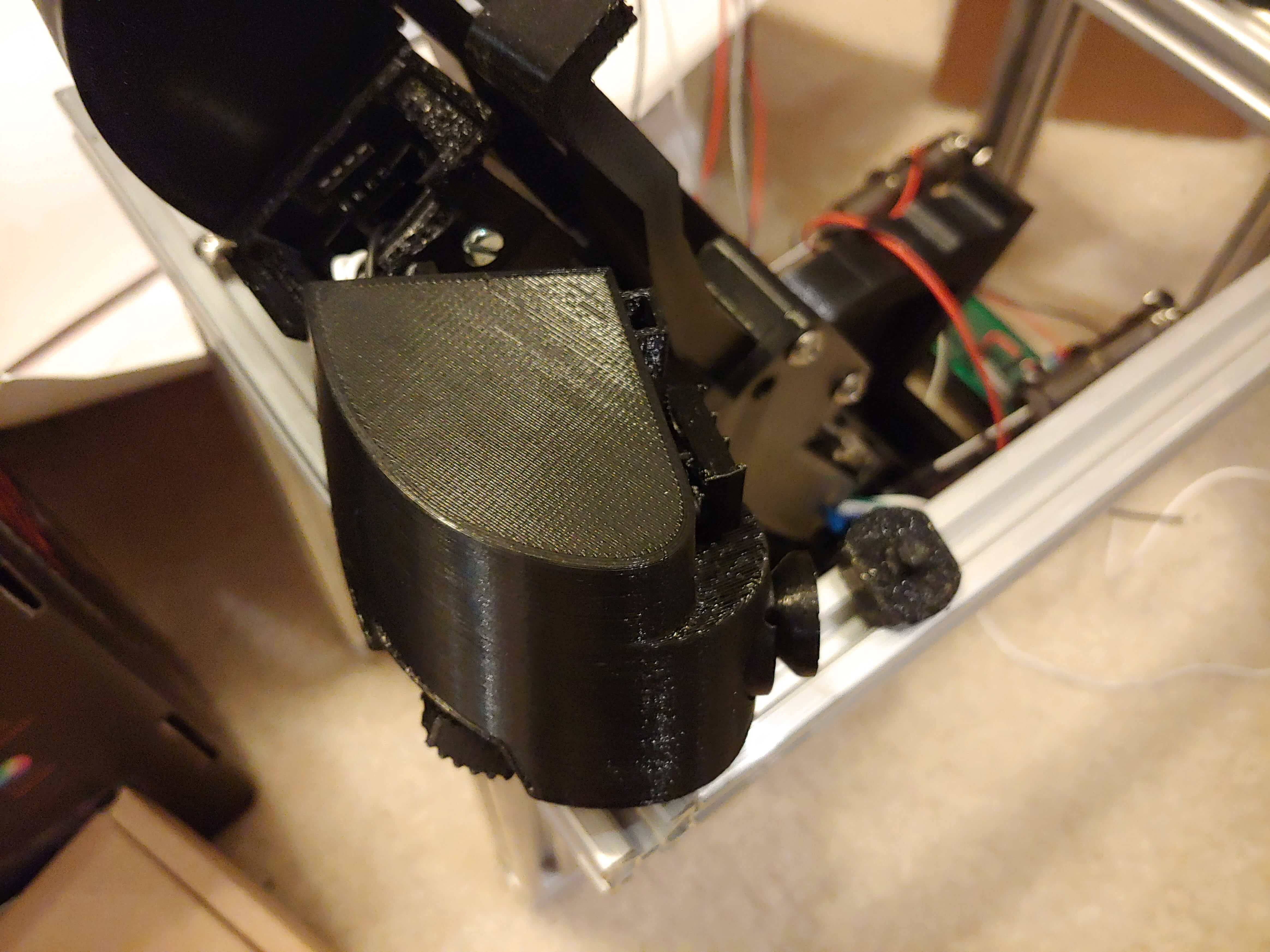
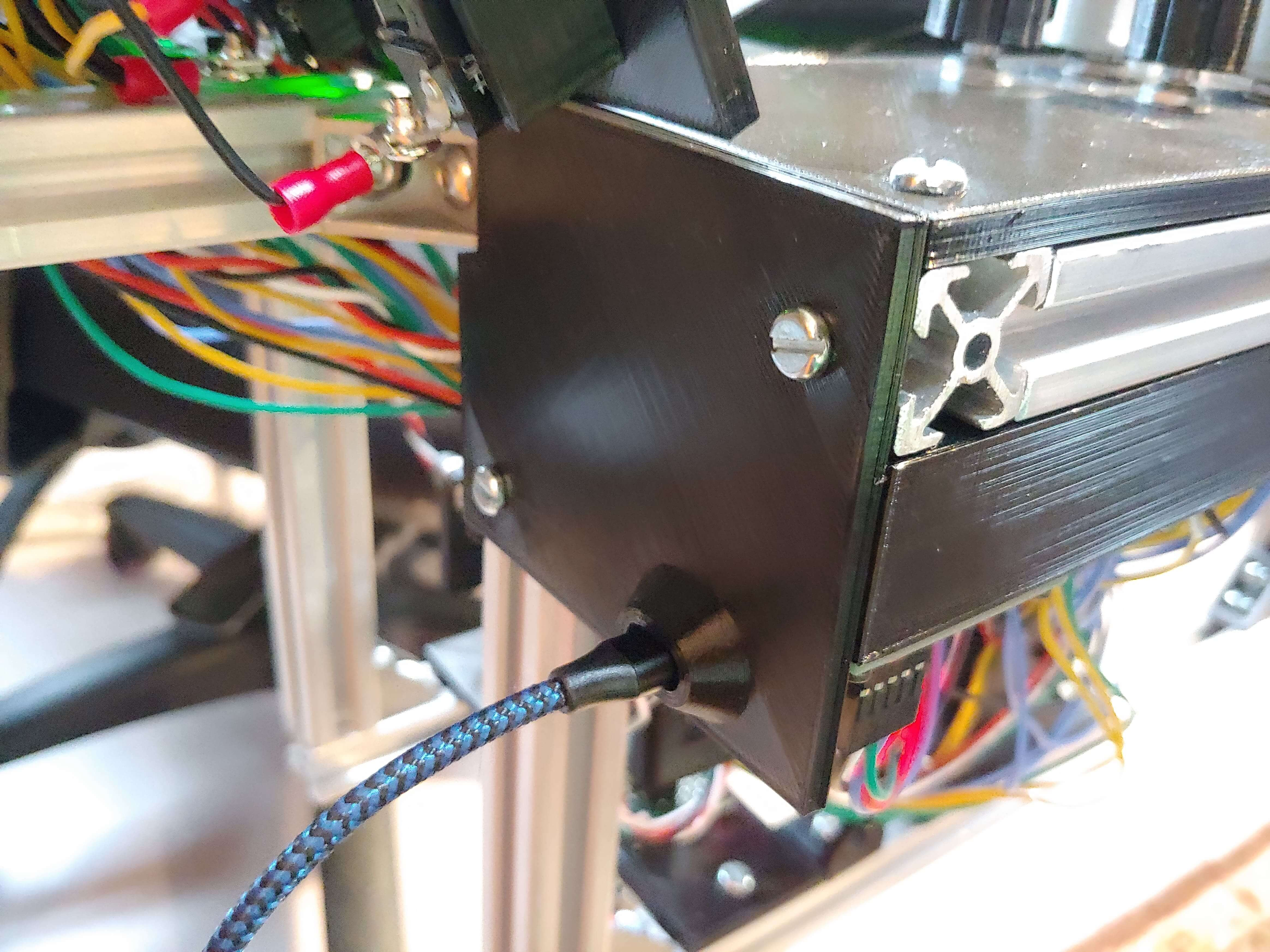
Another incident that led to a design change happened when I took the throttle off my desk without unplugging the USB cable, ripping the USB port off the Arduino. I spent hours replacing the broken Arduino, and I decided to design in strain relief to prevent this from happening again.
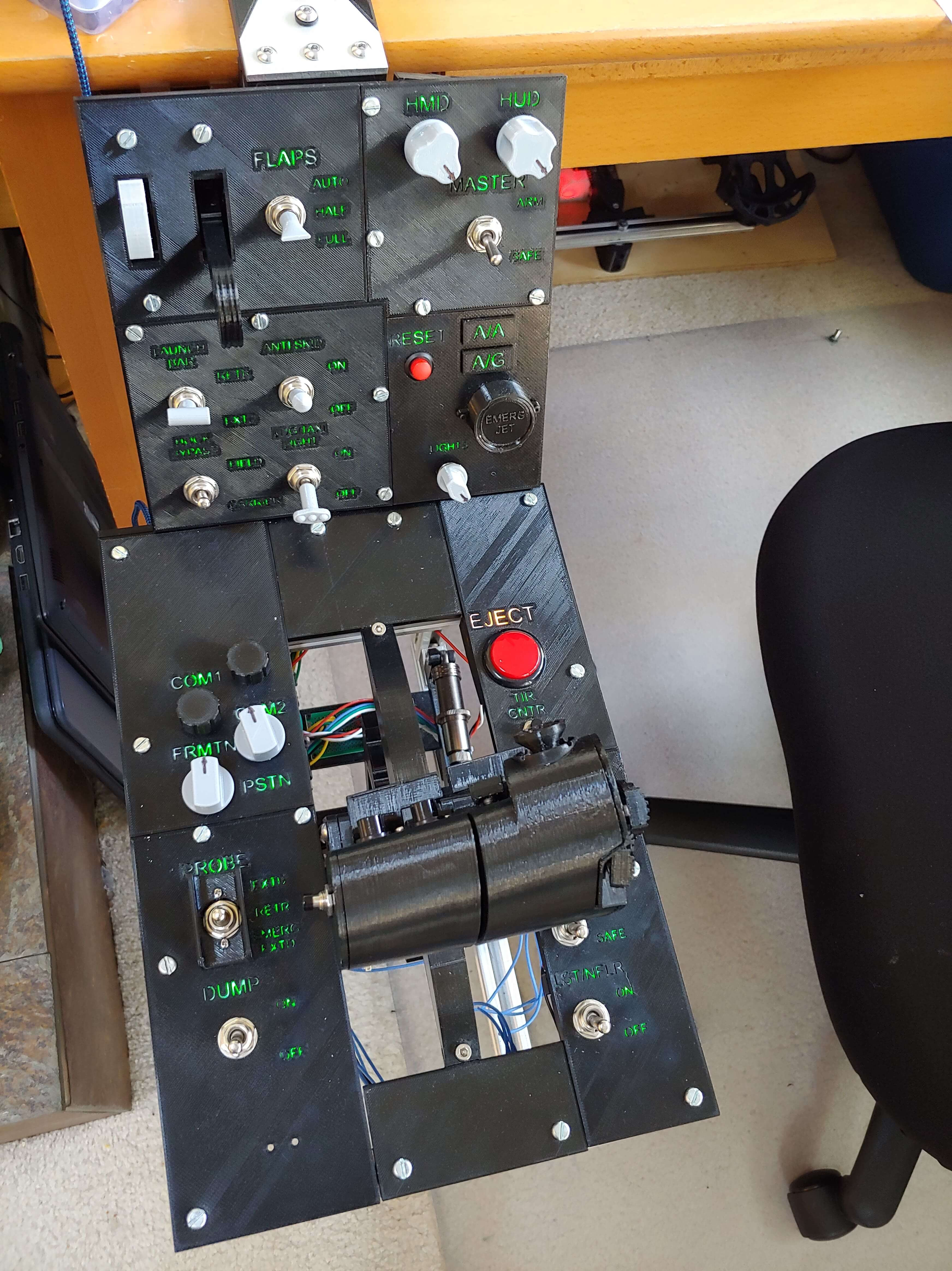
Switch Panels
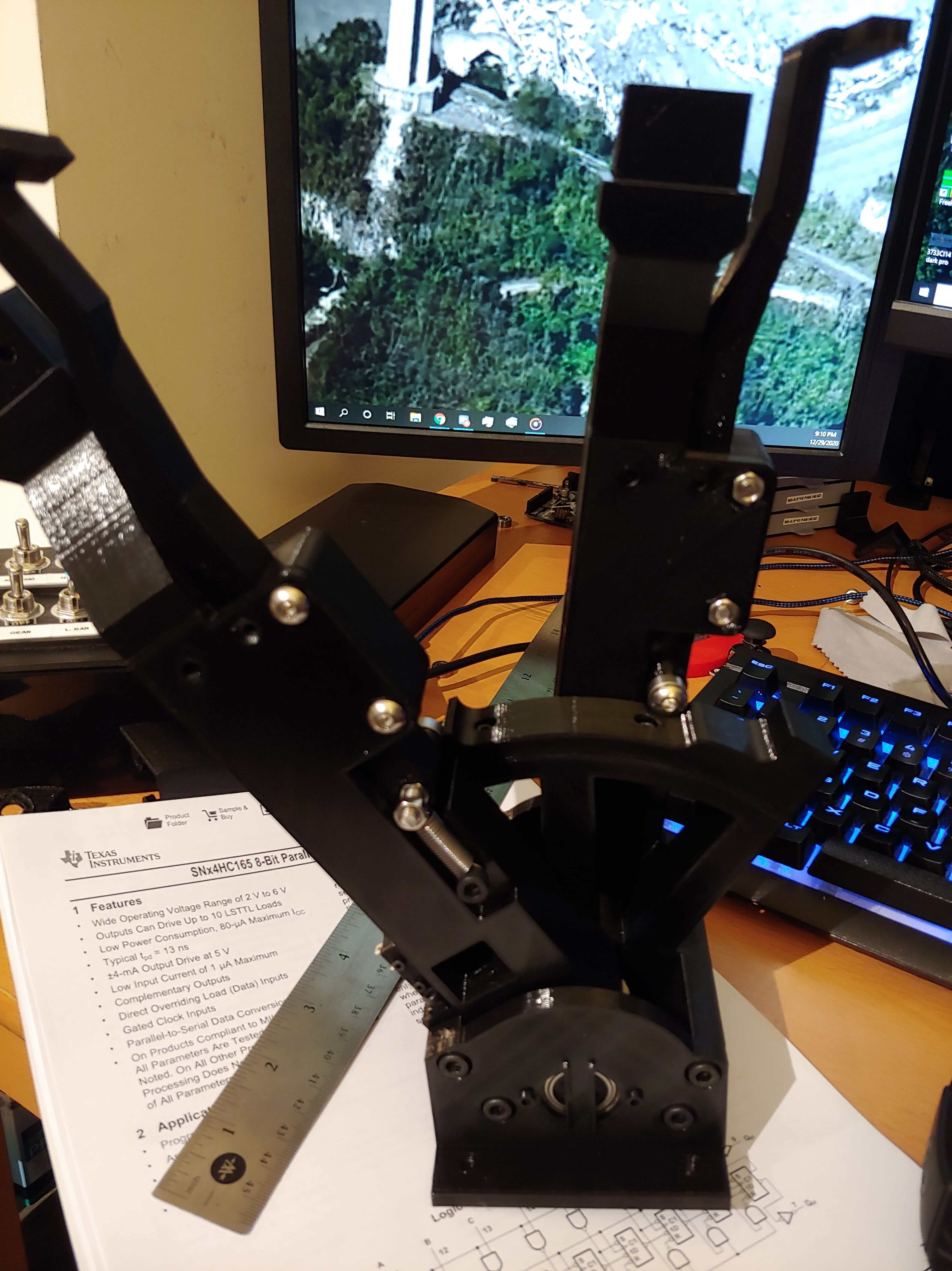
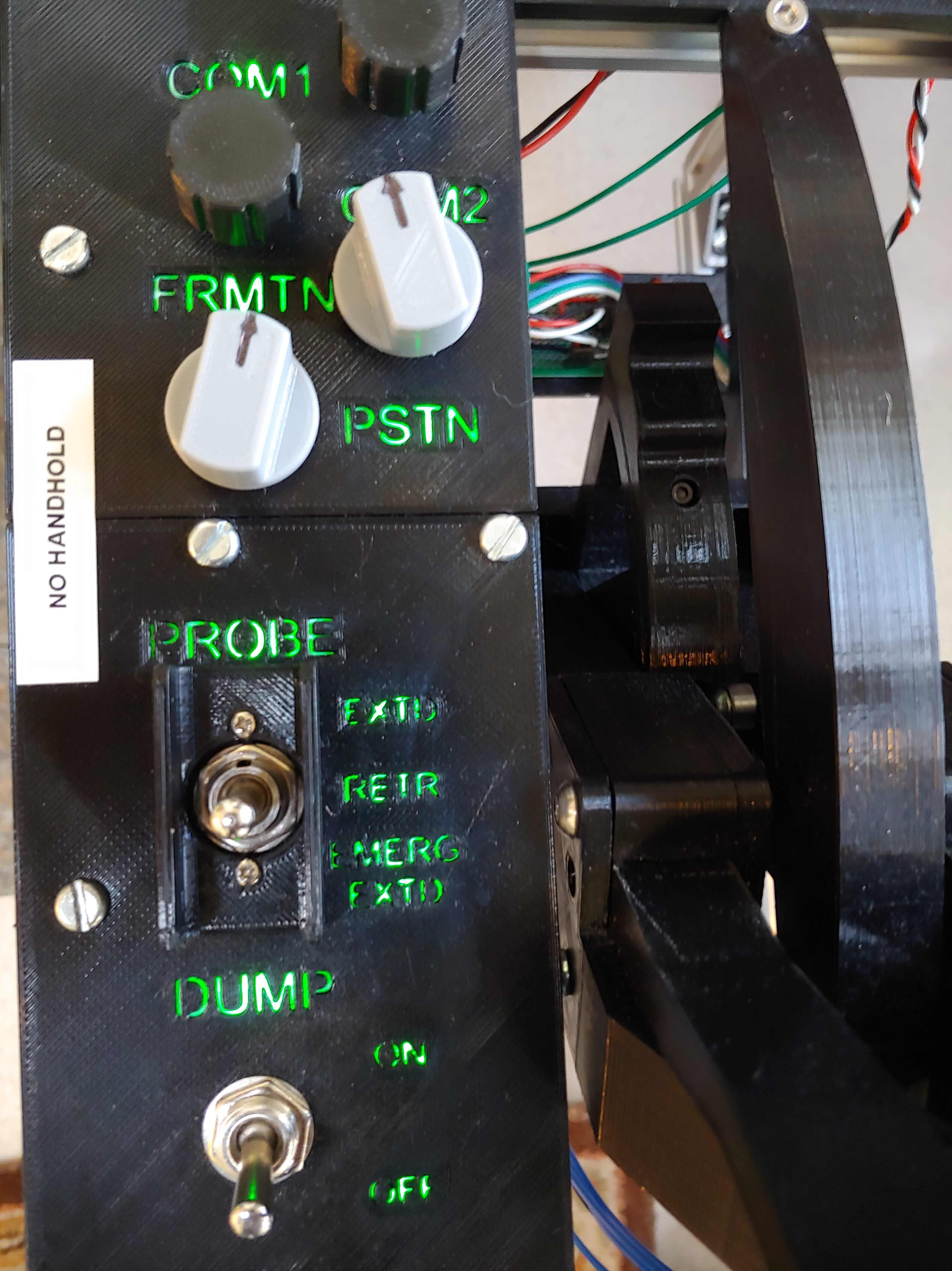
I finally had a working throttle, and I started playing DCS with it, while designing switch panels for the base. I used 12mm toggle switches for the tactile feel, and a couple potentiometers for various dials. I also used JumpNShootMan’s gear levers.
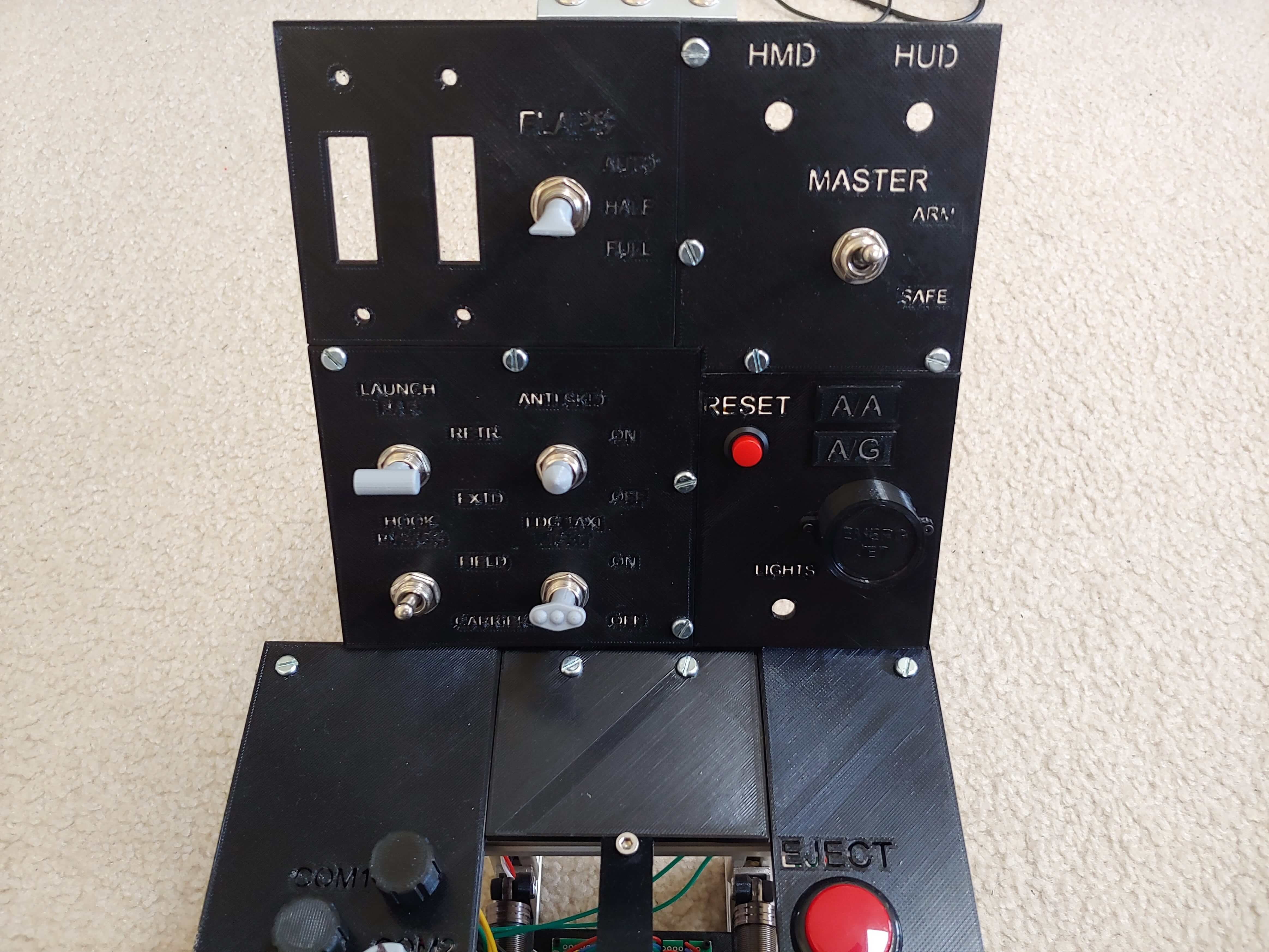
I designed in green backlighting for the switch labels, using a piece of paper as a really low quality diffuser.
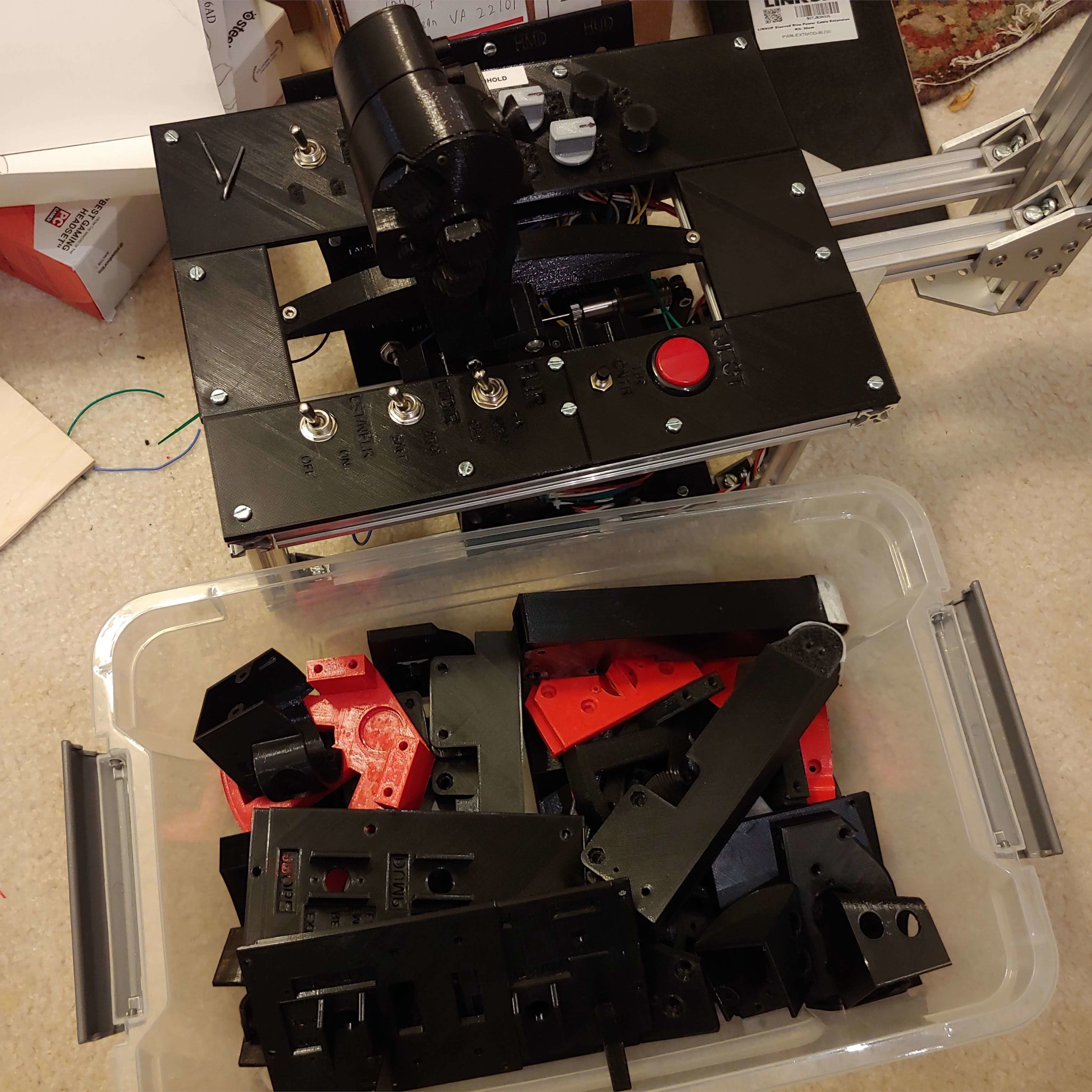
And with that, after 73 versions in Fusion, the hardware was complete. I had a full bin of discarded or broken printed parts, and I still have that bin in my room.
Code
Originally, I had planned to just use MMJoy2, but the framework struggled with handling nine shift registers and lacked some customizeability options that I needed, so I wrote my own code in Arduino using MHeironimus’s joystick library. The binding system used a massive array that was pretty jank, but it did end up working.
The Final Product